Shredder

A chopper and chopping technology, applied in grain processing and other directions, can solve the problems of high food waste rate, poor chopping effect, easy clogging, etc., to achieve low food waste rate, ensure chopping efficiency, and not block Effect

Inactive Publication Date: 2018-09-11
临武县小徐瓜瓜食品有限公司
View PDF15 Cites 0 Cited by
  • Summary
  • Abstract
  • Description
  • Claims
  • Application Information

AI Technical Summary

Problems solved by technology

[0003] Existing chopping mainly includes manual chopping with a kitchen knife and mechanical imitation of manual chopping. Manual chopping is time-consuming and laborious, and the chopping effect is not good. bad taste
When the mincers used for boneless meat are working, most of the outlets are designed with a round hole structure, which is easy to block, and if the outlet is not smooth and blocked, the boneless meat will be squeezed in the body and mutually If the rubbing time is too long, it will generate heat and squeeze out the juice, and the separation of the flesh and fibers will destroy the tissue structure of the boneless meat; and a large amount of food debris is attached to the inner wall of the body, which is not only difficult and demanding to clean, but also difficult to chop food. Uniform and delicate, the food waste rate is high, and the more the accumulation, the greater the frictional resistance when the body rotates, resulting in low power of the driving mechanism and affecting production efficiency; and it needs to be removed after each chopping, which cannot be operated continuously, and the operation is time-consuming and laborious

Method used


Image

  • Shredder
  • Shredder
  • Shredder

Examples


Embodiment 1

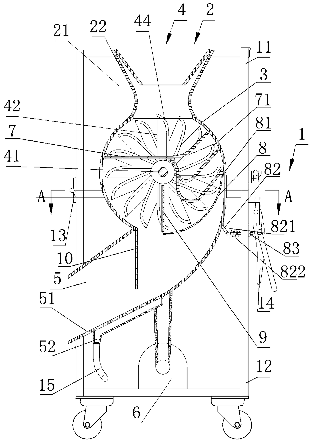
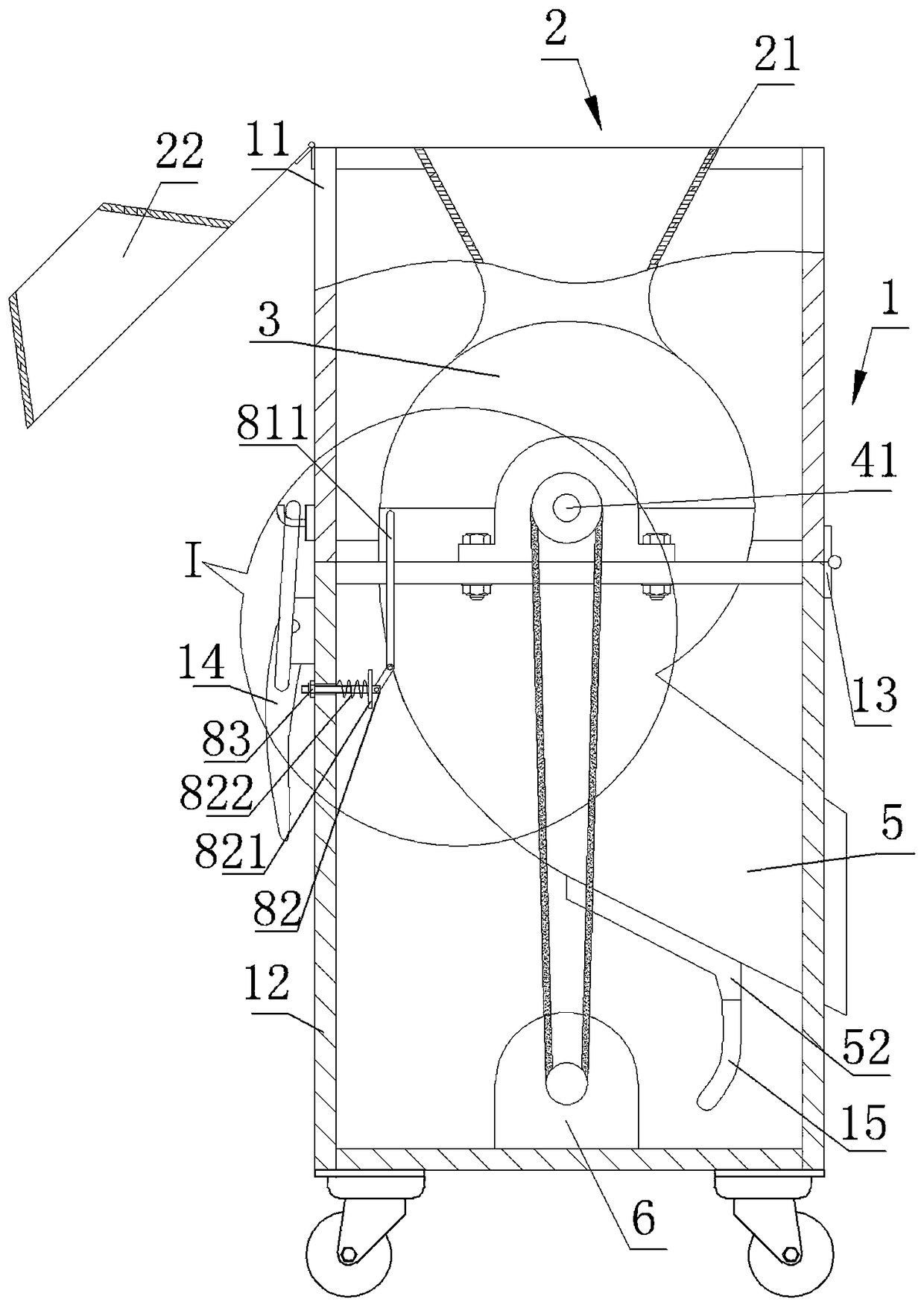
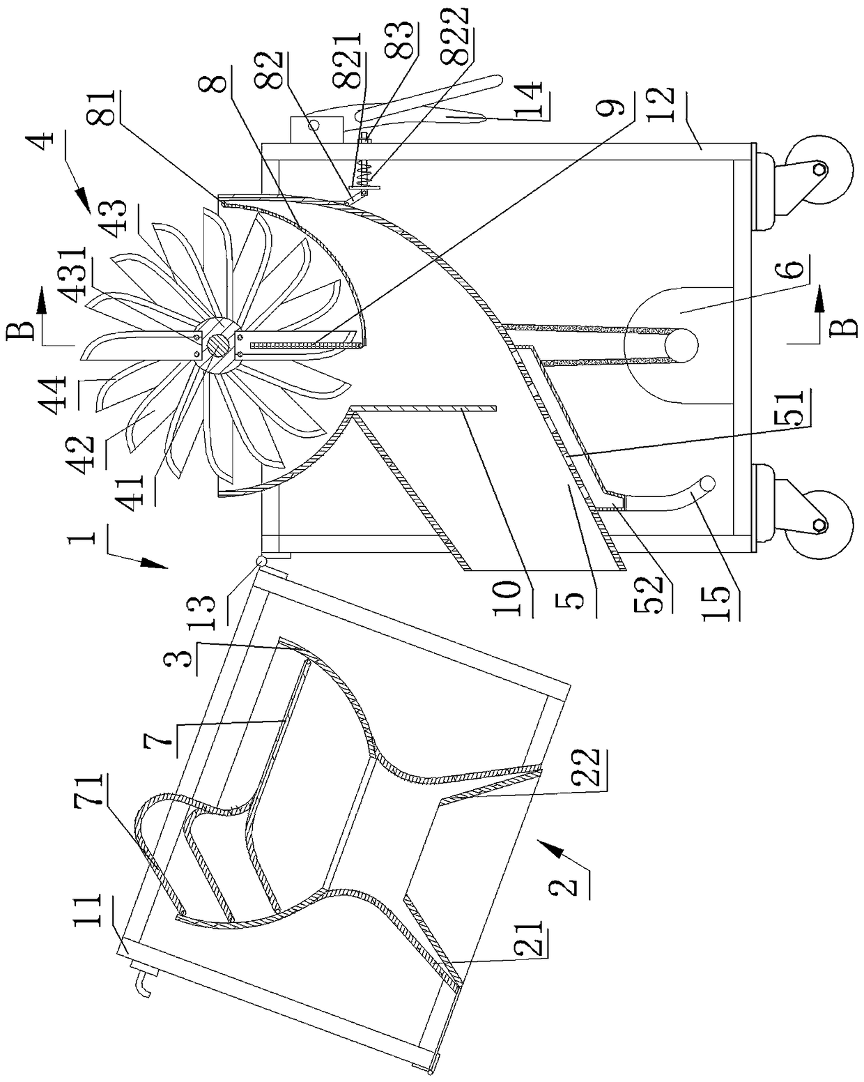
[0032] From Figure 1 to Figure 8It can be seen that this chopping machine of the present invention includes a casing 1, a feed hopper 2, a chopping cylinder 3, several combined cutters 4, a hopper 5, a motor 6, some auxiliary cutting rods 7, and arc adjustment Plate 8 and auxiliary cutting grid 9, wherein the chopping cylinder 3 is horizontally installed in the casing 1, each combined cutter 4 is installed on a rotating shaft 41 and is evenly arranged along the cylindrical helical line of the rotating shaft 41, and the rotating shaft 41 can rotate freely The axis of the penetrating chopping cylinder 3 is installed on the casing 1, each combined cutter 4 is installed in the chopping cylinder 3 through the rotating shaft 41, and each auxiliary cutting rod 7 is installed laterally in the chopping cylinder 3 above the rotating shaft 41, Each auxiliary cutting rod 7 is evenly arranged along the axial direction of the chopping cylinder 3, each auxiliary cutting rod 7 and the combin...

Embodiment 2

[0062] From Figure 9 It can be seen that the difference between the second embodiment and the first embodiment is that a roughing shell 16 is detachably installed on the upper shell 11 through bolts, and a rough-feeding shell 16 connected from top to bottom is provided in the roughing shell 16. Hopper 161 and coarsely chopping cylinder 162, the bottom of this coarsely chopping cylinder 162 is communicated with feed hopper 2, at the axial center of coarsely chopping cylinder 162 there are evenly installed some coarse combined cutters 163 along the helical line of the cylinder, A number of coarse auxiliary cutting rods 164 are evenly distributed in the coarse chopping cylinder 162 above the coarse combined cutter 163 along its axial direction, and each coarse combined cutter 163 and coarse auxiliary cutting rods 164 are arranged alternately along the coarse chopping cylinder 162 axial direction. , the thickness of the rough combination cutter 163 is greater than the combination...


PUM


Abstract

The invention discloses a mincing machine. The mincing machine comprises a machine shell, a feed hopper, a mincing cylinder, a plurality of combined cutters, a discharge hopper and a motor installed in the machine shell. A plurality of cutting assisting rods are evenly distributed in the mincing cylinder in the axial direction of the mincing cylinder, and a plurality of fulcrum rods are arranged on the cutting assisting rods on one side of the mincing cylinder from top to bottom. The cutting assisting rods are transversely connected to inner walls of the two sides of the mincing cylinder and used for containing products to be processed. An arc-shaped adjusting plate is arranged in the part, below the fulcrum rods, in the mincing cylinder. A cutting assisting bar is vertically installed in the part, at the upper end of the bottom of the adjusting plate, of the mincing cylinder. The adjusting plate can rotate around the cutting assisting bar to control the distance between the bottom of the adjusting plate and the cutting assisting bar. The combined cutters are evenly installed on an axis of the mincing cylinder along a cylinder spiral line through a rotation shaft. The combined cutters and the cutting assisting rods are distributed in the axial direction of the mincing cylinder in a staggered manner. The cutting assisting rods and grids of the cutting assisting bar are coaxially distributed in the axial direction of the mincing cylinder. The mincing machine is wide in application range, small in running resistance, high in discharging speed, fine and uniform in mincing, easy and safe to operate and easy to maintain and repair.

Description

technical field [0001] The invention relates to a food processing machine, in particular to a chopper. Background technique [0002] Whether in daily life or in the food processing industry, there will be situations where foods such as peppers, edible fungi, boneless meat and sweet potatoes are finely ground. At present, the commonly used fine crushing methods mainly include mincing and chopping. Among them, mincing is to use the rotating cutting blade to carry out preliminary shearing of the processed product, and then use the extrusion force of the screw and the shearing of the hole blade on the orifice plate. The food to be processed is chopped and discharged evenly, but due to the limitation of the action mode, it needs to pre-process the food before processing, and cut it into small pieces before it can be put into use; Next chop the product to be processed. The time required for the two kinds of processing is almost the same. The shape of the minced food is slightly ...

Claims


Application Information

Patent Timeline
Patent Type & Authority Patents(China)
IPC IPC(8): B02C18/14B02C18/18B02C18/22
CPCB02C18/142B02C18/145B02C18/18B02C18/2216
Inventor 罗金伟
Owner 临武县小徐瓜瓜食品有限公司
Why Eureka
Try Eureka