High-precision cut-out device and high-precision punching cut-out equipment thereof

A technology of cutting device and cutting equipment, which is applied in the field of mechanical parts processing, can solve problems such as errors and affecting the accuracy of plate strip 1a, and achieve the effects of saving costs, improving drilling efficiency, and ensuring accuracy

Inactive Publication Date: 2017-02-15
TAISHAN AIDA ELECTRICAL FACTORY
View PDF8 Cites 3 Cited by
  • Summary
  • Abstract
  • Description
  • Claims
  • Application Information

AI Technical Summary

Problems solved by technology

However, since the sensitivity of the photoelectric sensor is easily affected by the surrounding environment, only measuring the length of the sheet material 1a through the photoelectric sensor will easily cause large errors, thereby affecting the accuracy of the sheet material 1a

Method used


Image

  • High-precision cut-out device and high-precision punching cut-out equipment thereof
  • High-precision cut-out device and high-precision punching cut-out equipment thereof
  • High-precision cut-out device and high-precision punching cut-out equipment thereof

Examples


Embodiment 1

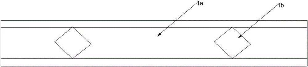
[0029] see figure 2 , The side of the plate strip to be cut is usually provided with a process hole 1c. The present invention makes full use of the positional relationship between the process hole 1c and the punching hole 1b of the sheet material to realize high-precision cutting of the sheet material.

[0030] see Figure 4 , which is a schematic structural diagram of Embodiment 1 of the high-precision cutting device of the present invention. The high-precision cutting device 10 includes a length detection mechanism 11 , a cutting positioning mechanism 12 , a cutting mechanism 13 and a control mechanism. The length detection mechanism 11 is arranged on one side of the plate strip 1a to be conveyed, and is used for detecting the length of the plate strip 1a. The cutting and positioning mechanism 12 is periodically inserted into the process hole 1c of the plate strip 1a for positioning. The cutting mechanism 13 is arranged between the length detection mechanism 11 and the ...

Embodiment 2

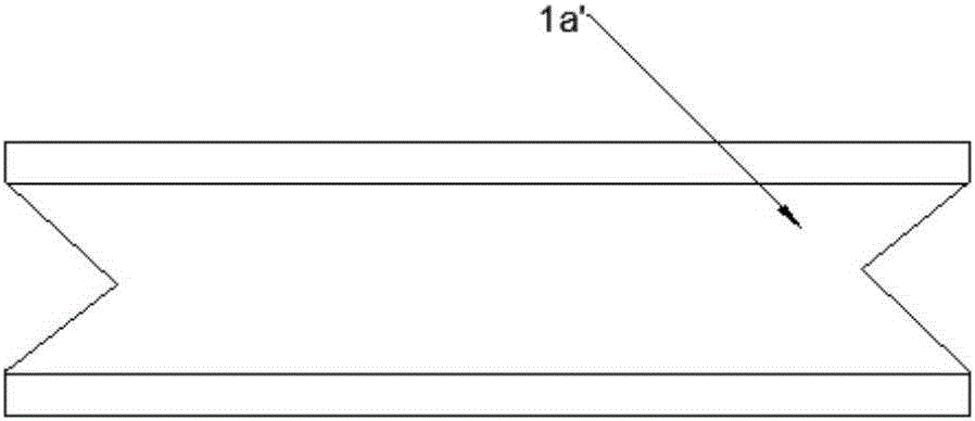
[0041] The high-precision cutting device of this embodiment includes a punching device 20 , a cold roll forming machine and a cutting device arranged along the conveying direction of the plate strip 1a. The punching device 20 is used for punching holes on the sheet material strip 1a; the cold roll forming machine continuously bends the sheet material strip material transversely, and bends the sheet material strip material 1 to form a process hole 1c. After the cutting device is positioned according to the process hole 1c, it cuts off the plate strip 1a along the punching hole.

[0042] see Figure 7 , which is a schematic structural view of the punching device in Example 2. The punching device 20 includes a feeding mechanism 21 , a punching mechanism 22 and a punching positioning mechanism 23 arranged in sequence along the conveying direction of the plate strip 1a. The feeding mechanism 21 is used to continuously transport the sheet material strip to the punching mechanism 2...


PUM


Abstract

The invention relates to a high-precision cut-out device. The high-precision cut-out device comprises a length detection mechanism, a cut-out positioning mechanism and a cut-out mechanism. The length detection mechanism is arranged on one side of a to-be-conveyed panel strip and used for detecting the length of the panel strip. The cut-out positioning mechanism is inserted in an auxiliary hole of the panel strip and used for positioning the panel strip. The cut-out mechanism is arranged between the length detection mechanism and the cut-out positioning mechanism and used for cutting out the panel strip after the cut-out positioning mechanism is inserted in the auxiliary hole. Compared with the prior art, after the length of the panel strip is detected through the length detection mechanism and the panel strip is positioned through the cut-out positioning mechanism, the panel strip is cut out, the cut-out precision is ensured, the cost for manually cutting out the panel strip is greatly saved, and the cut-out efficiency is improved. Meanwhile, the invention relates to high-precision punching cut-out equipment.

Description

technical field [0001] The invention relates to the field of machining of mechanical parts, in particular to a high-precision cutting device and high-precision punching and cutting equipment. Background technique [0002] Please also see Figure 1 to Figure 3 , figure 1 is a schematic diagram of the top view structure of the strip to be cut off; figure 2 is a schematic diagram of the side view structure of the strip to be cut off; image 3 It is a schematic diagram of the top view structure after the strip material is cut. In the field of mechanical parts processing, it is usually necessary to punch a hole 1b on the plate strip 1a first, and then cut the plate strip along the punched hole 1b to obtain the plate strip 1a' of the required specification. [0003] In the prior art, when the plate strip 1a is cut, usually according to the length of the specified plate strip 1a, a photoelectric sensor is placed on one side of the plate strip 1a conveying direction, and the le...

Claims


Application Information

Patent Timeline
Patent Type & Authority Applications(China)
IPC IPC(8): B21D28/02B21D28/04B21C51/00B21D35/00B21D28/26B21D43/00
CPCB21D28/02B21C51/00B21D28/04B21D28/26B21D35/001B21D35/002B21D43/003
Inventor 雷勉仪
Owner TAISHAN AIDA ELECTRICAL FACTORY
Why Eureka
Try Eureka