Mold plunger chip stretching and drawing type punching mechanism

A mold punch, telescopic technology, applied in the field of mold punch telescopic punching mechanism, can solve problems such as unrealizable, unrealizable corrugated board punching position, adjustment, etc., to achieve reasonable structure, simple structure, and avoid bending reverse effect

Active Publication Date: 2017-02-15
ZHEJIANG WILLING TECH +1
View PDF7 Cites 2 Cited by
  • Summary
  • Abstract
  • Description
  • Claims
  • Application Information

AI Technical Summary

Problems solved by technology

In daily use, continuous punching is required on corrugated boards. At present, the common punching of corrugated boards is realized through the joint action of the punch on the upper punching roller and the die of the lower punching roller. The punch (that is, the punch) is fixed, so that the adjustment of the punching position of the corrugated board cannot be realized. If it is necessary to punch both ends of a long corrugated board, the middle section does not punch. Hole device will not be able to achieve

Method used


Image

  • Mold plunger chip stretching and drawing type punching mechanism
  • Mold plunger chip stretching and drawing type punching mechanism

Examples


Embodiment Construction

[0013] The present invention will be further described in detail below in conjunction with the accompanying drawings and examples. The following examples are explanations of the present invention and the present invention is not limited to the following examples.

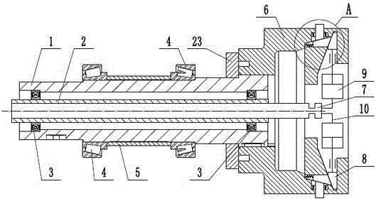
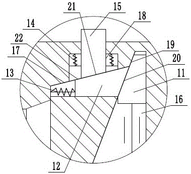
[0014] Such as figure 1 and figure 2 As shown, a telescopic punching mechanism for a die punch includes an upper roller 1, a rigid air pipe 2, a deep groove ball bearing 3, a tapered roller bearing 4, a bearing support sleeve 5, an upper punch roller 6, and a rotary joint 7 . Telescopic punch assembly 8, the upper roller 1 is a hollow shaft, the rigid air pipe 2 is installed in the upper roller 1 through a deep groove ball bearing 3, and two tapered roller bearings 4 are arranged on the outer side of the upper roller 1 , A bearing support sleeve 5 is arranged between the two tapered roller bearings 4 to realize the support and positioning of the two tapered roller bearings 4 . The upper punching roller 6 is rigid...


PUM


Abstract

The invention provides a mold plunger chip stretching and drawing type punching mechanism, and belongs to the technical field of metal forming. The mold plunger chip stretching and drawing type punching mechanism comprises an upper roller, an upper punching roller wheel and a stretching and drawing plunger chip component. The upper punching roller wheel and the upper roller are rigidly connected. A rotating connector is arranged at one end of a rigid air pipe. The stretching and drawing plunger chip component is arranged in the upper punching roller wheel in an equal-distance and equal-angle mode. A first adjusting block of the stretching and drawing plunger chip component is arranged in a first sliding groove of the upper punching roller wheel in a radially slidable mode, and a second adjusting block is arranged in a second sliding groove of the upper punching roller wheel in an axially slidable mode. A first inclined surface of the first adjusting block is attached to a second inclined surface of the second adjusting block, a plunger chip is arranged in a third sliding groove of the upper punching roller wheel in a radially slidable mode, and a fourth inclined surface of the plunger chip is attached to a third inclined surface of the second adjusting block. An air cylinder is fixedly arranged in the upper punching roller wheel and connected with the rotating connector through a flexible air pipe, and a piston rod of the air cylinder is connected with the first adjusting block. According to the mold plunger chip stretching and drawing type punching mechanism, the purpose that the plunger chip stretches out and draws back can be achieved, adjustment of the punching position of a corrugated sheet can be achieved, and the structure is reasonable.

Description

technical field [0001] The invention relates to the technical field of metal forming, in particular to a telescopic punching mechanism of a mold punch. Background technique [0002] Corrugated board is also called profiled plate. It adopts color coated steel plate, galvanized sheet and other metal sheets to be rolled and cold-bent into various corrugated profiled plates. It is suitable for industrial and civil buildings, warehouses, special buildings, large-span Roof, wall and interior and exterior wall decoration of steel structure houses. It has the characteristics of light weight, high strength, rich color, convenient and quick construction, earthquake resistance, fire prevention, rain resistance, long life, maintenance-free, etc., and has been widely promoted and applied. Especially in the construction industry, more and more color-coated steel sheets are pressed into metal forming sheets of various shapes. The substrates of these corrugated sheets are cold-rolled steel...

Claims


Application Information

Patent Timeline
IPC IPC(8): B21D28/26
CPCB21D28/26
Inventor 张洋肖军妹杨桂灿
Owner ZHEJIANG WILLING TECH
Why Eureka
Try Eureka