
Washer and motor bearing system comprising the same

a technology of motor bearings and washers, which is applied in the direction of machines/engines, manual lubrication, distribution equipment, etc., can solve the problems of high cost, troublesome installation, and fast abrasion, and achieve the effects of low production cost, convenient installation, and simple structur

Active Publication Date: 2013-02-19
ZHONGSHAN BROAD OCEAN MOTOR MFG
View PDF7 Cites 0 Cited by
  • Summary
  • Abstract
  • Description
  • Claims
  • Application Information

AI Technical Summary

Benefits of technology

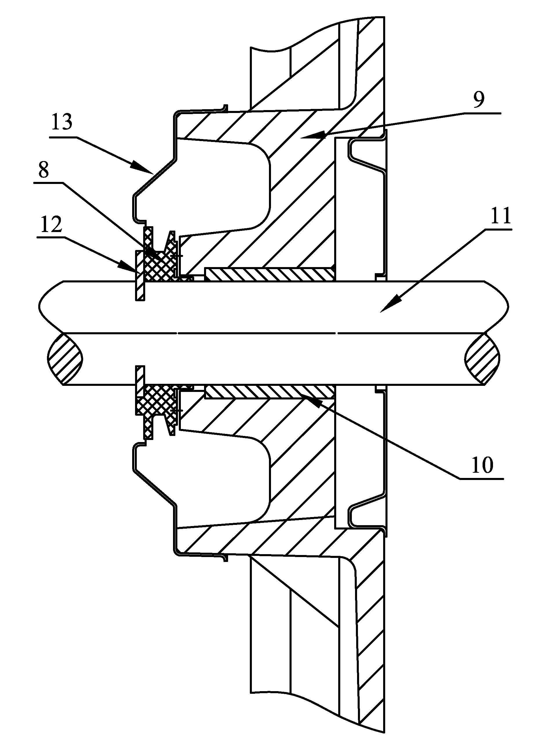
The invention is a washer and a motor bearing system that have good oil keeping and return effect, preventing oil from entering a motor body, and ensuring normal operation of the motor. The washer is simple in structure, operates to replace multiple components of a conventional bearing system, and features low production cost, and convenient installation. The oil-storage groove on the washer reduces friction between the washer and contact surface, such as the end surface of the bearing, and that of the end cover, and thus abrasion is slight, work life is greatly increased, and effective operation of the motor is ensured. The second flange axially extending from the second oil retainer of the washer is combined with the retaining ring, and rotates along with the rotating shaft, which increases axial torsion applied on the rotating shaft, and no relative rotation occurs therebetween, which prevents redundant friction, and increases work life of the rotating shaft.

Problems solved by technology

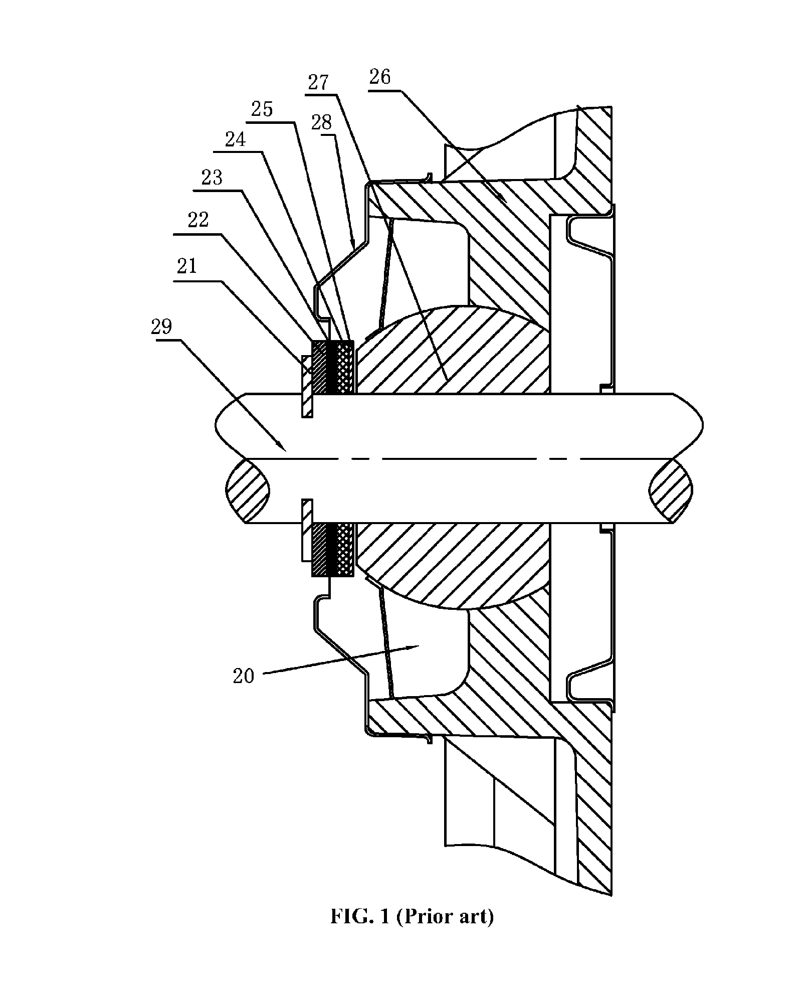
However, the structure has the following disadvantages: 1) the number of components is too large, which leads to complex structure, troublesome installation, and high cost; 2) during operation of the motor, the rotating shaft 29 rotates along with the axial retaining ring 21, the positioning retaining ring 22, the adjusting retaining ring 23, the rubber washer 24, and the wear-resistant pad 25, surface of the wear-resistant pad 25 is rough and not lubricant enough, and thus friction force generated as being contacted with contact surface, such as end surface of the end cover 26, and that of the bearing, is comparatively large, which leads to fast abrasion of the wear-resistant pad 25, and thus affecting work life of the whole system; 3) structure composed of the positioning retaining ring 22, the adjusting retaining ring 23, the rubber washer 4, the wear-resistant pad 25, and the oil cap 8 features poor oil retaining and return effect, and oil leakage often occurs, as lubricating oil keeps leaking and is not enough, lubricating effect of the bearing 27 becomes poor, which affects normal operation of the motor, reduces work life of the oil bearing, and causes failure of the motor.

Method used


Image

  • Washer and motor bearing system comprising the same
  • Washer and motor bearing system comprising the same
  • Washer and motor bearing system comprising the same

Examples


Embodiment Construction

[0025]Further description of the invention will be given below in conjunction with specific embodiments and accompanying drawings.

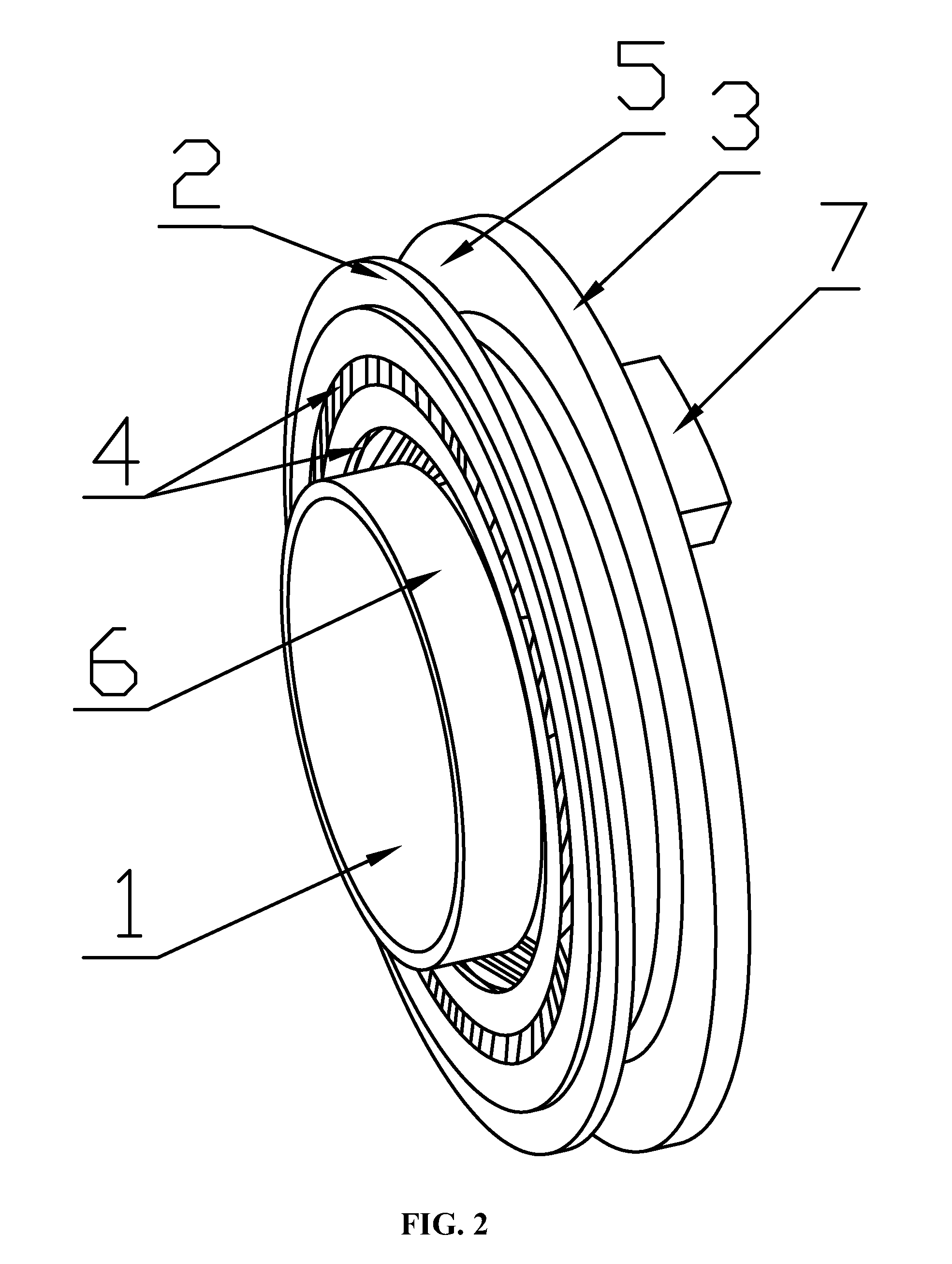
[0026]As shown in FIGS. 2 and 3, a washer of the invention comprises a central axial hole 1, a first oil retainer 2, a second oil retainer 3, and a transition groove 5.

[0027]The central axial hole 1 allows a motor shaft to pass therethrough.

[0028]The first oil retainer 2 is formed on one side of the washer 8.

[0029]At least one oil-storage groove 4 is disposed on the surface of the first oil retainer 2. The oil-storage groove 4 is an annular groove.

[0030]The second oil retainer 3 is disposed at the back of the first oil retainer 2. A diameter of the second oil retainer 3 is greater than or equal to that of the first oil retainer 2, and a transition groove 5 is disposed between the first oil retainer 2 and the second oil retainer 3.

[0031]The transition groove 5 is an annular groove.

[0032]A first flange 6 axially extends from the first oil retainer 2, and a ...


PUM


Abstract

A washer, including a central axial hole, a first oil retainer, a second oil retainer, and a transition groove. The central axial hole allows a motor shaft to pass therethrough. The first oil retainer and the second oil retainer are formed on the washer. The transition groove is disposed between the first oil retainer and the second oil retainer.

Description

CROSS-REFERENCE TO RELATED APPLICATIONS[0001]This application is a continuation of International Patent Application No. PCT / CN2010 / 070299 with an international filing date of Jan. 21, 2010, designating the United States, now pending, and further claims priority benefits to Chinese Patent Application No. 200920054053.6 filed on Mar. 31, 2009. The contents of all of the aforementioned applications, including any intervening amendments thereto, are incorporated herein by reference.BACKGROUND OF THE INVENTION[0002]1. Field of the Invention[0003]The invention relates to a washer, and a motor bearing system comprising the same.[0004]2. Description of the Related Art[0005]As shown in FIG. 1, a conventional motor bearing system is illustrated, and comprises an end cover 26, a rotating shaft 29, a bearing 27, an oil cap 28, an axial retaining ring 21, a positioning retaining ring 22, an adjusting retaining ring 23, a rubber washer 24, and a wear-resistant pad 25. An oil-storage groove 20 is ...

Claims


Application Information

Patent Timeline
Patent Type & Authority Patents(United States)
IPC IPC(8): F16N1/00
CPCF16C33/6655F16C33/74H02K5/1672F16C2380/26H02K5/16H02K5/15
Inventor LI, YINGCHENGZHANG, SHEN
Owner ZHONGSHAN BROAD OCEAN MOTOR MFG
Learn More