
Flange end face machining device

A technology of end face processing and flanges, which is applied in the field of flange end face processing devices, can solve the problems of high construction cost, long time-consuming flange assembly and disassembly and maintenance, etc.

Inactive Publication Date: 2017-02-15
丁乐冲
View PDF9 Cites 10 Cited by
  • Summary
  • Abstract
  • Description
  • Claims
  • Application Information

AI Technical Summary

Problems solved by technology

[0004] In order to overcome the deficiencies of the prior art, such as long time-consuming flange installation and disassembly and maintenance, and high construction costs, the present invention provides a flange end face processing device that is easy to operate and use, avoids flange assembly and disassembly, and has low construction costs.

Method used


Image

  • Flange end face machining device

Examples


Embodiment Construction

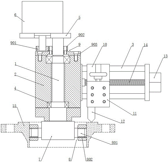
[0013] exist figure 1 Among them, a flange end face processing device includes a fixed shaft 1 , a rotating sleeve 2 and a parallel guide rail 3 . Wherein, the rotating sleeve 2 is rotatably arranged on the fixed shaft 1 via the rotating supporting member 4 .

[0014] Such as figure 1 As shown, in this embodiment, a deep groove ball bearing and a tapered roller bearing are preferred for the rotating support member 4, the deep groove ball bearing is used to bear the radial load of the rotating sleeve 2, and the tapered roller bearing bears the radial load of the rotating sleeve 2 The radial load is used to bear the axial load of the rotating sleeve 2 at the same time. The two bearings cooperate to rotate and support the two ends of the rotating sleeve 2 on the fixed shaft 1, so that the rotating sleeve 2 can rotate with high precision, flexibility and reliability, and can effectively prevent the rotation of the sleeve 2. During the process, the "stuck" phenomenon occurs.

[...


PUM


Abstract

The invention discloses a flange end face machining device for solving the problem that an existing flange takes a long time for assembly, disassembly and maintenance and is high in construction cost. The flange end face machining device comprises a fixing shaft, a rotating sleeve and parallel guide rails, and is characterized in that the rotating sleeve is rotationally arranged on the fixing shaft through a rotary supporting part; a driving motor is mounted on one end of the fixing shaft through a fixing frame; a fixing seat is coaxially arranged on the other end of the fixing shaft; a plurality of fixing parts are symmetrically and uniformly distributed in the radial direction and on the circumferential surface of the fixing seat; an output shaft of the driving motor is used for driving the rotating sleeve to rotate by virtue of a transmission part; the parallel guide rails are horizontally fixed on the rotating sleeve; a cutting knife holder is arranged on the parallel guide rails in a sliding manner; a cutting knife rest is longitudinally arranged on the cutting knife holder in a sliding manner; a knife is assembled on the cutting knife rest; the cutting knife rest is used for driving the knife to implement longitudinal feeding on the cutting knife holder; a feeding motor arranged at the end parts of the parallel guide rails is used for driving the cutting knife holder to move horizontally by virtue of a ball screw. The flange end face machining device disclosed by the invention is capable of preventing assembly and disassembly of a flange, convenient to operate and use and low in construction cost.

Description

technical field [0001] The invention relates to a turning device specially suitable for special workpieces, especially a flange end face processing device. Background technique [0002] We know that the flange is a workpiece widely used in working environments such as pressure vessels, tanks, and pipelines. Due to the need for tightness of the connecting surface, the roughness and flatness of the flange end face are required to be high. During the processing and installation of the flange, the end face of the flange is often damaged by bumps, resulting in leakage of the equipment; in addition, during the use of the equipment, the end face of the flange is also prone to cavitation, which affects the sealing of the equipment. Therefore, it is very important to process and repair the damaged flange end face in time. [0003] The existing common practice is to unload the flange from the equipment it is assembled on, refix it to a large milling and boring machine for processing ...

Claims


Application Information

Patent Timeline
IPC IPC(8): B23B5/00B23Q3/12B23B21/00B23Q5/40B23Q5/28
CPCB23B5/00B23Q1/25B23Q3/12B23Q5/28B23Q5/40
Inventor 丁乐冲
Owner 丁乐冲
Learn More