
Side plate in-situ positioning fixture for ceiling laser brazing system

A technology for positioning fixtures and side panels, applied to laser welding equipment, welding equipment, manufacturing tools, etc., can solve the problems of increased material costs and labor costs, and poor appearance, so as to reduce equipment-preparation time and improve the appearance of the car body , Improve the effect of brazing quality

Active Publication Date: 2020-11-06
HYUNDAI MOTOR CO LTD +1
View PDF1 Cites 0 Cited by
  • Summary
  • Abstract
  • Description
  • Claims
  • Application Information

AI Technical Summary

Problems solved by technology

[0009] However, in the conventional process, since the roof molding is connected to the welded part of the side panel and roof panel, the appearance is not very good, and the material cost and labor cost will increase due to the connection of the roof molding

Method used


Image

  • Side plate in-situ positioning fixture for ceiling laser brazing system
  • Side plate in-situ positioning fixture for ceiling laser brazing system
  • Side plate in-situ positioning fixture for ceiling laser brazing system

Examples


Embodiment Construction

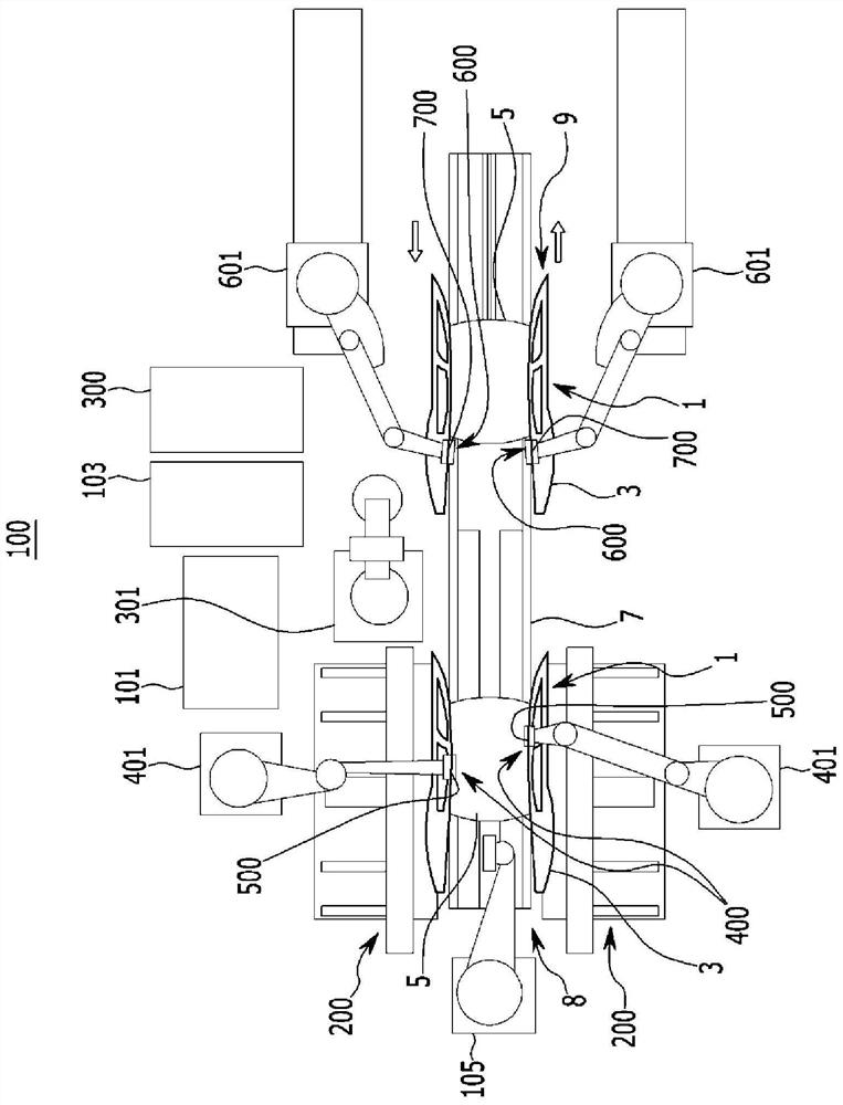
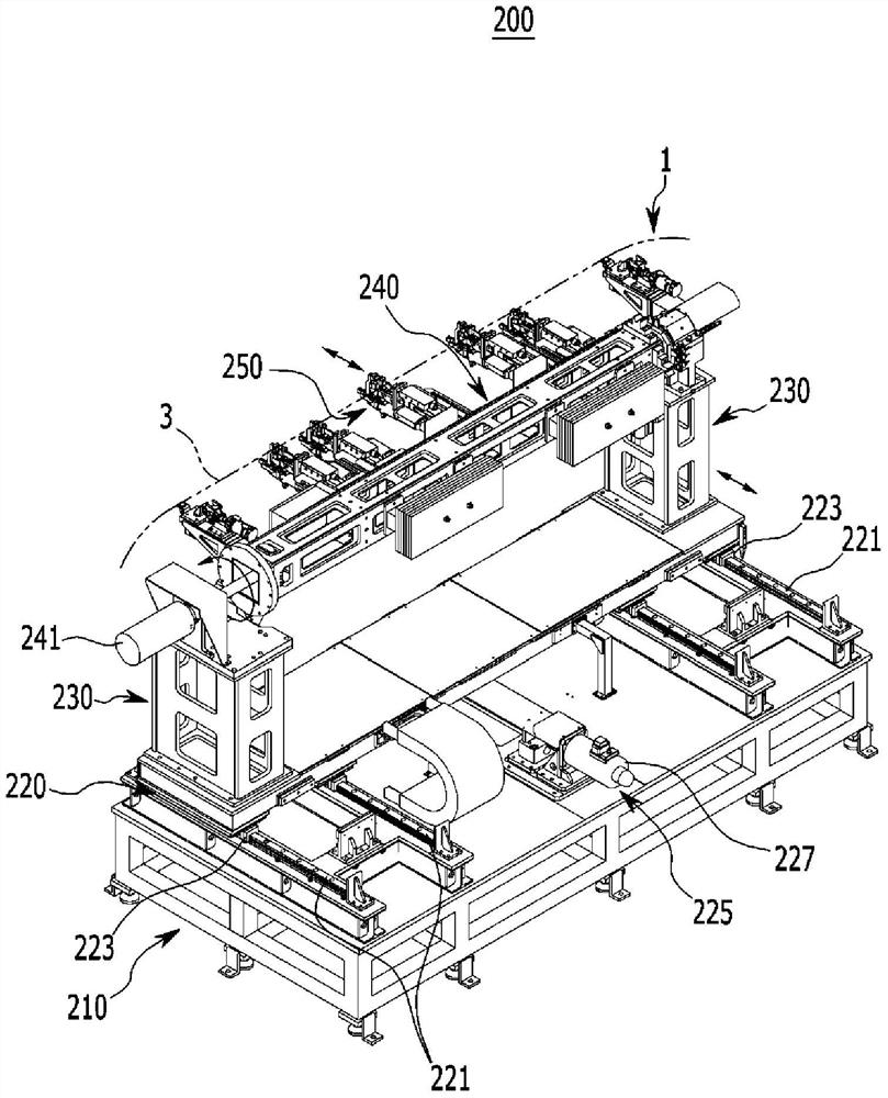
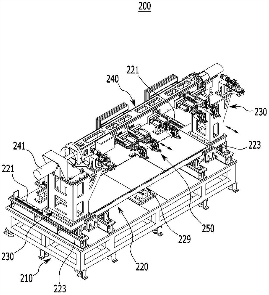
[0094] Hereinafter, the present invention will be described in detail with reference to the accompanying drawings, in which embodiments of the present invention are illustrated. Those skilled in the art will appreciate that various changes can be made in these embodiments without departing from the spirit of the invention.

[0095] Accordingly, the drawings and description are to be regarded as illustrative in nature and not restrictive. In the specification, the same or equivalent reference numerals refer to the same or equivalent components.

[0096] In the drawings, the size and thickness of each configuration are arbitrarily shown for understanding and convenience of expression, but the present invention is not limited thereto, and the thicknesses of layers, films, plates, regions, etc. may be exaggerated for clarity in the drawings.

[0097] In the following description, the distinction of component names by "first", "second", etc. is to distinguish based on the same com...


PUM


Abstract

A side panel home-positioning jig is configured to hold and home-position an opposite side panel of a body in a roof laser-brazing system, the roof laser-brazing system configured with a predetermined brazing section and a predetermined grinding section along a transferring path of the body and configured to bond a roof panel to opposite side panels based on the body that includes the opposite side panels. The side panel home-positioning jig includes: a base frame configured to be installed in the brazing section at one of opposite sides of the transferring path between which the transferring path extends; a moving frame configured to be reciprocally and slidably movable in a width direction of the body; a post frame disposed in a direction perpendicular to opposite sides of the moving frame; a support frame installed at the post frame along a length direction of the opposite side panels; and a plurality of clampers mounted on the support frame along the transfer direction of the body, the plurality of clampers configured to be reciprocally movable in the width direction of the body, and to hold the opposite side panels.

Description

[0001] Cross References to Related Applications [0002] This application claims priority from Korean Patent Application No. 10-2015-0108920 filed with the Korean Intellectual Property Office on Jul. 31, 2015, the entire contents of which are incorporated herein by reference. technical field [0003] The present invention relates to body assembly systems. More specifically, the present invention relates to a roof laser brazing system for assembling side panels and roof panels of a vehicle body. Background technique [0004] In general, a vehicle body is formed into a body in white (BIW) through a body assembly process of assembling various panels produced in a body sub-process. [0005] The vehicle body includes a floor panel forming a lower side of a body frame, side panels forming left and right sides of the body frame, a roof panel forming a top of the body frame, a plurality of roof rails, a cowl panel, a rear panel, and Parcel racks, etc. These parts of the body are ...

Claims


Application Information

Patent Timeline
IPC IPC(8): B23K3/08B23K37/04B23K1/005B23K26/00
CPCB23K1/0056B23K3/087B23K26/0093B23K37/0435B23K2101/006B23K1/0008B23K26/032B23K26/0838B23K26/0884B23K37/0443B23K37/047B23K2101/18
Inventor 陈泰昕沈旻宣崔正豪
Owner HYUNDAI MOTOR CO LTD
Learn More