Laser-driven hydro-bugling board riveting method and structure

A hydraulic bulging, laser-driven technology, used in laser welding equipment, welding equipment, welding/welding/cutting items, etc., can solve the problems of complex production efficiency and reliability, complex special devices, small lateral deformation, etc. The effect of large production flexibility, high production reliability, and reduced possibility of damage

Active Publication Date: 2017-02-15
SHANDONG UNIV
View PDF10 Cites 8 Cited by
  • Summary
  • Abstract
  • Description
  • Claims
  • Application Information

AI Technical Summary

Problems solved by technology

[0006] This method solves the problem of small lateral deformation in the existing method, and can form a large amount of interlocking embedding, thereby improving the connection s

Method used


Image

  • Laser-driven hydro-bugling board riveting method and structure
  • Laser-driven hydro-bugling board riveting method and structure

Examples


Embodiment 1

[0044] Embodiment 1: A laser-driven hydraulic bulging plate riveting method mainly includes the following steps:

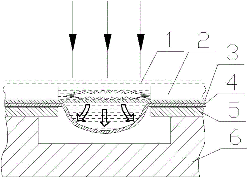
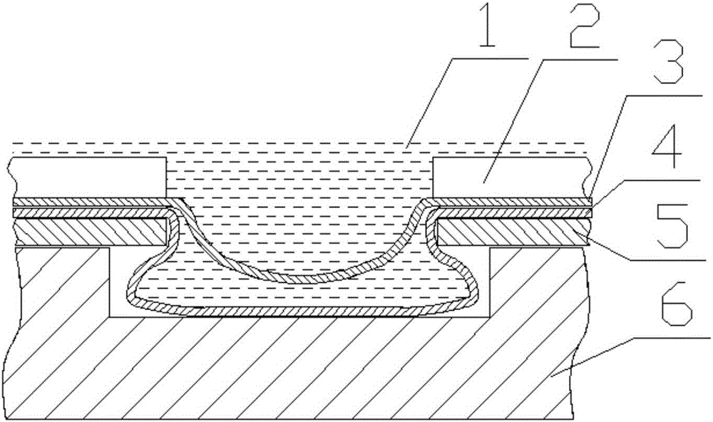
[0045] (a) placing the lower sheet material 5 and the middle layer sheet material 4 with a bulge on the forming mold 6 in sequence, and the center of the bulge structure of the middle layer sheet material 4 is aligned with the center of the riveted position of the lower layer sheet material 5;

[0046] (b) Inject transparent liquid 1 to fill the bulging structure of the middle layer plate 4;

[0047] (c) Place the upper plate 3 above the middle plate 4, and then use the pressing device 2 to compress each layer of plate;

[0048] (d) In order to enhance the laser impact effect, inject transparent liquid 1 on the upper part of the upper plate 3, the depth is not greater than 5mm;

[0049] (d) if figure 1 As shown, the surface of the upper plate 3 is irradiated with a pulsed laser, and explosive plasma is formed on the surface of the upper plate 3. The explosive pl...

Embodiment 2

[0056] Embodiment 2: A laser-driven hydraulic bulging plate riveting method mainly includes the following steps:

[0057] (a) placing multiple layers of bulging middle-layer sheets 4 on top of the split-type lower-layer sheet 5 in sequence, and aligning the center of the bulging structure of the middle-layer sheet 4 with the geometric center of the through hole of the lower-layer sheet 5;

[0058] (b) Inject transparent liquid 1 to fill the bulging structure of the middle layer plate 4;

[0059] (c) Place the upper plate 3 above the middle plate 4, and then use the pressing device 2 to compress each layer of plate;

[0060] (d) In order to enhance the laser impact effect, inject transparent liquid 1 on the upper part of the upper plate 3, the depth is not greater than 5mm;

[0061] (d) Using pulsed laser to irradiate the surface of the upper plate 3, forming explosive plasma on the surface of the upper plate 3, the explosive plasma impacts the surface of the upper plate 3, th...


PUM


Abstract

The invention relates to a laser-driven hydro-bugling board riveting method and structure, and belongs to the field of advanced laser manufacturing. The laser-driven hydro-bugling board riveting method mainly comprises the steps that A, a lower board is placed on a forming mold provided with a groove, and the lower board is provided with a through hole; B, an intermediate board is placed on the lower board, and the intermediate board is provided with a bump located in the through hole; C, liquid is injected into the bump, and an upper board is placed on the intermediate board; D, the upper board is pressed by means of a pressing device; and E, the upper board is impacted through laser light, so that the upper board deforms downwards, impact force is transmitted to the bump through the liquid in the bump, the bump is made to generate transverse and longitudinal deformation towards the space below the through hole, and thus the intermediate board and the lower board are riveted. According to the laser-driven hydro-bugling board riveting method and structure, unidirectional impact force is changed into multidirectional force through the liquid, high-strength riveting of different boards is achieved by means of simple equipment, and the cost is extremely low.

Description

technical field [0001] The invention relates to the field of advanced laser manufacturing, in particular to a laser-driven hydraulic bulging plate riveting method and structure, which are used to realize rivetless riveting between plates. Background technique [0002] Plate riveting, especially rivetless riveting technology, has been more and more widely used in automobile and aircraft industries, and various advanced riveting technologies have developed rapidly. [0003] In the prior art, there have been some studies on rivetless riveting technology. For example, the Chinese patent document with the application number 200810014018.1 proposes a pulse laser micro-riveting method and special device for ultra-thin plates. This method uses the explosive plasma induced by the pulsed laser beam to impact the plate into a riveting buckle with a small mouth and a large bottom. shape, so that the upper and lower plates are riveted together. Compared with the traditional riveting me...

Claims


Application Information

Patent Timeline
IPC IPC(8): B23K26/122B23K26/20B21J15/00B23K101/16
CPCB21J15/00B23K26/1224B23K26/20B23K2101/16
Inventor 季忠王建峰梁萌郑超刘韧
Owner SHANDONG UNIV
Why Eureka
Try Eureka