Battery module welding clamp and battery module welding device

A technology of battery modules and welding fixtures, applied in auxiliary devices, welding equipment, auxiliary welding equipment, etc., can solve problems such as high cost and achieve the effect of improving welding efficiency

Active Publication Date: 2017-02-15
NEUSOFT REACH AUTOMOTIVE TECH SHANGHAI CO LTD
View PDF5 Cites 18 Cited by
  • Summary
  • Abstract
  • Description
  • Claims
  • Application Information

AI Technical Summary

Problems solved by technology

[0004] The purpose of the present invention is to provide a battery module welding jig and a battery module welding device to solve the technical problem of high cost caused by the pressing of different structural fixtures for modules of different structures

Method used


Image

  • Battery module welding clamp and battery module welding device
  • Battery module welding clamp and battery module welding device
  • Battery module welding clamp and battery module welding device

Examples


Embodiment Construction

[0061] Reference will now be made in detail to the exemplary embodiments, examples of which are illustrated in the accompanying drawings. When the following description refers to the accompanying drawings, the same numerals in different drawings refer to the same or similar elements unless otherwise indicated. The implementations described in the following exemplary examples do not represent all implementations consistent with the present invention. Rather, they are merely examples of apparatuses and methods consistent with aspects of the invention as recited in the appended claims.

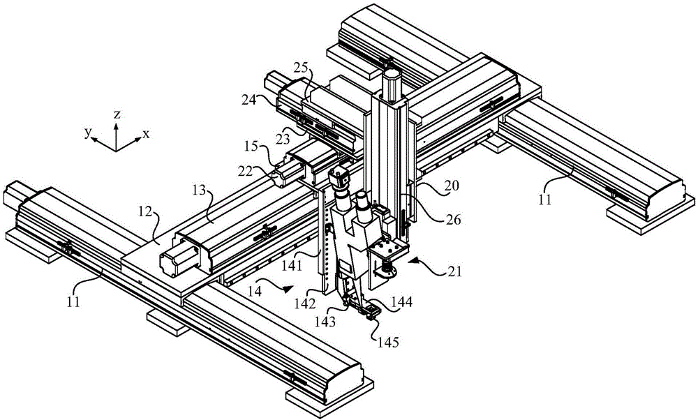
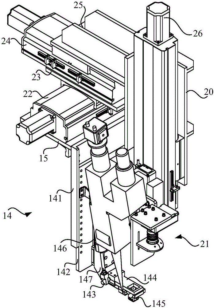
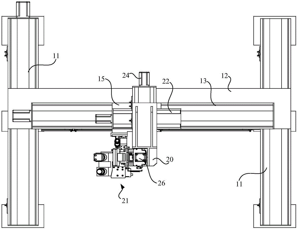
[0062] figure 1 is a structural schematic diagram of a battery module welding jig shown according to an exemplary embodiment, image 3 It is a top view of a battery module welding jig according to an exemplary embodiment. Such as figure 1 with image 3 As shown, a battery module welding jig includes a traveling mechanism mounted on a workbench and a pressing assembly 14 . The traveling mech...


PUM


Abstract

The invention relates to a battery module welding clamp and a battery module welding device. The battery module welding clamp comprises a walking mechanism erected on a work table and a downward pressing assembly fixed to the walking mechanism and used for downwards pressing a battery module on the work table when the walking mechanism moves the downward pressing assembly to the welding position. The downward pressing assembly downwards presses the battery module on the work table, and completes operation of single-point pressing of the battery module on the welding position, the clamp does not need to be replaced for products of different structures, the technical problem that modules of different structures need to be pressed by clamps of different structures, and high cost is caused is solved, and the welding efficiency is improved.

Description

technical field [0001] The invention relates to the technical field of welding automation, in particular to a battery module welding jig and a battery module welding device. Background technique [0002] The traditional welding fixture is to determine the fixture structure and press-fit method according to the size of the module. Each module can only use one kind of fixture, and the production line requires production efficiency. A line will make many fixtures according to the production cycle, and the clamping of the fixtures The position will not change due to the welding position. In this way, products with different structures need to be pressed with fixtures of different structures. After the production of the products is completed, the corresponding fixtures will also become waste products, and the cost is very high. At the same time, the time required to install the fixture before welding and disassemble the fixture after welding will be very long, which will affect ...

Claims


Application Information

Patent Timeline
Patent Type & Authority Applications(China)
IPC IPC(8): B23K37/02B23K37/04
CPCB23K37/0247B23K37/0252B23K37/0443
Inventor 刘双刘博渊武斌斌
Owner NEUSOFT REACH AUTOMOTIVE TECH SHANGHAI CO LTD
Why Eureka
Try Eureka