
Pneumatic wrench semi-automation device

A semi-automated wrench technology, applied in the direction of portable mobile devices, motor tools, manufacturing tools, etc., can solve the problems of difficult production and manufacturing, large assembly quantity, inconvenient manual operation, etc., and achieve easy operation, improved assembly quality, and saving The effect of manual labor intensity

Inactive Publication Date: 2017-02-15
CRRC BEIJING ERQI VEHICLE CO LTD
View PDF5 Cites 0 Cited by
  • Summary
  • Abstract
  • Description
  • Claims
  • Application Information

AI Technical Summary

Problems solved by technology

[0002] In the manufacturing process of railway freight cars, the coupler buffer device is a very critical part, and its performance is directly related to the safety of the vehicle during driving. Therefore, higher requirements are put forward for the assembly quality of the coupler buffer device. All bolts have tightening torque requirements, which must meet the corresponding regulations of the national standard, and those that do not meet the regulations are judged as unqualified products, which will bring difficulties to the manufacturer.
[0003] During production and manufacture, the fastening bolts need to be pre-tightened before the assembly of the coupler buffer device. However, due to the space limitation of the car body structure, manual operation is very inconvenient when assembling the fastening bolts, and the assembly quantity of each vehicle is large, so Assembly changes are required to meet production needs

Method used


Image

  • Pneumatic wrench semi-automation device

Examples


Embodiment Construction

[0013] The present invention will be described in detail below in conjunction with the accompanying drawings. However, it should be understood that the accompanying drawings are provided only for better understanding of the present invention, and they should not be construed as limiting the present invention.

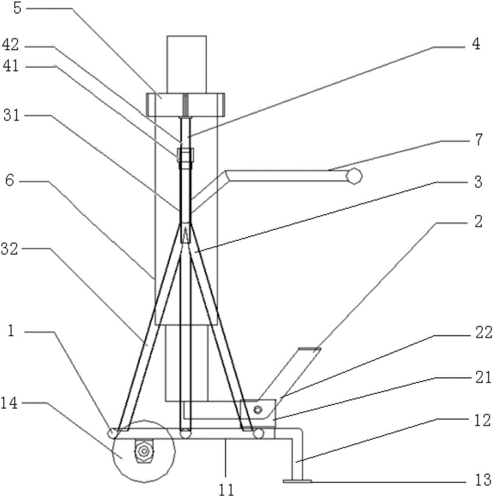
[0014] Such as figure 1 As shown, the pneumatic wrench semi-automatic device of the present invention includes a support base 1, a pedal drive frame 2, two fixed supports 3, two movable supports 4, an annular fixed seat 5 and a pneumatic wrench 6;

[0015] One end of the top of the support base 1 is movably connected to the pedal drive frame 2, and two fixed supports 3 are arranged in parallel on both sides of the top of the support base 1, and the top of each fixed support 3 is fixedly connected to the ring-shaped fixed seat 5 through a movable support 4, and the wind-driven The upper part of the wrench 6 passes through the annular fixing seat 5 and is fixedly connect...


PUM


Abstract

The invention relates to a pneumatic wrench semi-automation device. The pneumatic wrench semi-automation device is characterized in that the device comprises a support base, a fixed support, a pedal driving frame, a pneumatic wrench, a movable support, an annular fixer and a handle; a walking wheel is fixedly arranged at one side of the bottom of the support base, a support bottom plate is fixedly arranged at the other side of the bottom of the support base, one end of the top of the support base is movably connected with the pedal driving frame, the fixed support is fixedly arranged at the two sides of the top of the support base, the top of the fixed support is connected with the annular fixer through the movable support, the upper part of the pneumatic wrench penetrates through the annular fixer and is fixedly connected with the annular fixer, the bottom of the pneumatic wrench is fixedly connected with one end of the pedal driving frame, and one side of the fixed support is provided with the handle in an outward extension manner. The pneumatic wrench semi-automation device is simple to operate and can be widely applied to the assembly of a fastening bolt in a railway vehicle coupler buffering device.

Description

technical field [0001] The invention relates to a pneumatic wrench semi-automatic device for assembling fastening bolts in a coupler buffer device of a railway vehicle, and relates to the technical field of railway vehicles. Background technique [0002] In the manufacturing process of railway freight cars, the coupler buffer device is a very critical part, and its performance is directly related to the safety of the vehicle during driving. Therefore, higher requirements are put forward for the assembly quality of the coupler buffer device. All bolts have tightening torque requirements, which must meet the corresponding regulations of the national standard, and those that do not meet the regulations are judged as unqualified products, which will bring difficulties to the manufacturer. [0003] During production and manufacture, the fastening bolts need to be pre-tightened before the assembly of the coupler buffer device. However, due to the space limitation of the car body s...

Claims


Application Information

Patent Timeline
IPC IPC(8): B25B21/00B25F5/00
CPCB25B21/00B25B21/002B25F5/00
Inventor 闫保营张瑞增王秀琴李霞章超荣许静李艳琴杨海林杨传丰宋玉亮胡松林刘伟李昌霍零春张世颖
Owner CRRC BEIJING ERQI VEHICLE CO LTD
Learn More