
Loading and unloading dual-purpose mechanical arm

A robotic arm and dual-purpose technology, applied in the field of dual-purpose robotic arms for loading and unloading, can solve problems such as increasing costs, and achieve the effects of saving time, facilitating unloading, and saving investment costs

Inactive Publication Date: 2017-02-15
NANLING ZINGIBER MIOGA ROSE IND ASSOC
View PDF0 Cites 1 Cited by
  • Summary
  • Abstract
  • Description
  • Claims
  • Application Information

AI Technical Summary

Problems solved by technology

[0002] With the development and progress of society, robotic arms have gradually replaced the position of manpower in physical labor. The existing robotic arms include handling robotic arms, loading robotic arms, unloading robotic arms, and picking robotic arms. Nowadays, in factories A lot of physical labor has been replaced by robotic arms, but factories usually need to introduce loading robotic arms and unloading robotic arms to do the work. When one of the loading robotic arm and unloading robotic arm is damaged, the other will be damaged. It is difficult for the mechanical arm to replace the damaged mechanical arm, which greatly increases the cost of the factory

Method used


Image

  • Loading and unloading dual-purpose mechanical arm
  • Loading and unloading dual-purpose mechanical arm
  • Loading and unloading dual-purpose mechanical arm

Examples


Embodiment Construction

[0019] The following will clearly and completely describe the technical solutions in the embodiments of the present invention with reference to the accompanying drawings in the embodiments of the present invention. Obviously, the described embodiments are only some, not all, embodiments of the present invention.

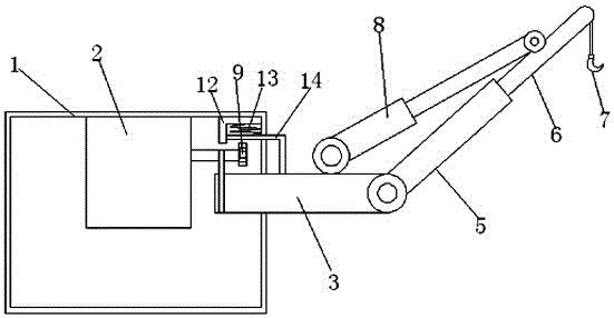
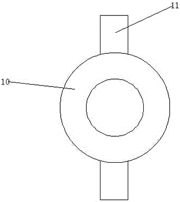
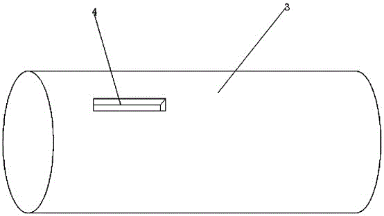
[0020] refer to Figure 1-4 , a dual-purpose mechanical arm for loading and unloading, including a base 1 with a hollow structure, a motor 2 is installed on the top inner wall of the base 1, and a screw 3 is connected to the outer wall of one side of the base 1 through a bearing, and the screw 3 is located on the motor. 2, the screw 3 extends into the base 1, and the screw 3 is connected to the output shaft of the motor 2 through a belt. The first groove 4 is an axisymmetric figure, and the axis of symmetry is the diameter of the screw rod 3. The end of the screw rod 3 away from the base 1 is rotatably connected to a female rod 5 with a hollow structure, and a sub-ro...


PUM


Abstract

The invention discloses a loading and unloading dual-purpose mechanical arm. The loading and unloading dual-purpose mechanical arm comprises a base of a hollow structure. An electromotor is mounted on the inner wall of the top of the base. The outer wall of one side of the base is connected with a screw rod through a bearing. The screw rod is located below the electromotor. The screw rod extends into the base. The screw rod is in transmission connection with an output shaft of the electromotor through a belt. The outer wall of the screw rod is provided with two grooves. The two grooves are located on the outer side of the base. The two grooves are in axial symmetry. The symmetry axis of the two grooves is the diameter of the screw rod. A mother rod of a hollow structure is rotatably connected to the end, far from the base, of the screw rod. A son rod is slidably mounted in the mother rod. An iron hook is connected to the end, far from the mother rod, of the son rod. The loading and unloading dual-purpose mechanical arm has a loading state and an unloading state and can be freely switched between the loading state and the unloading state. The investment cost of loading and unloading is lowered in different forms, and the time is saved.

Description

technical field [0001] The invention relates to the technical field of loading and unloading mechanical arms, in particular to a dual-purpose loading and unloading mechanical arm. Background technique [0002] With the development and progress of society, robotic arms have gradually replaced the position of manpower in physical labor. The existing robotic arms include handling robotic arms, loading robotic arms, unloading robotic arms, and picking robotic arms. Nowadays, in factories A lot of physical labor has been replaced by robotic arms, but factories usually need to introduce loading robotic arms and unloading robotic arms to do the work. When one of the loading robotic arm and unloading robotic arm is damaged, the other will be damaged. It is difficult for the mechanical arm to replace the damaged mechanical arm, which greatly increases the cost of the factory. Contents of the invention [0003] The purpose of the present invention is to solve the shortcomings in th...

Claims


Application Information

Patent Timeline
IPC IPC(8): B25J9/12
CPCB25J9/12
Inventor 刘和勇
Owner NANLING ZINGIBER MIOGA ROSE IND ASSOC
Learn More