A ground automatic phase separation device and its control method

An automatic phase separation and grounding technology, which is applied in the direction of transportation and packaging, power lines, vehicle parts, etc., can solve the problems of inability to accurately determine the thyristor turn-off point, long dead zone of power failure in the neutral zone, and low service life of mechanical switches. Achieve high economy and practicability, improve service life and perfect protection function

Active Publication Date: 2020-01-10
ZHUZHOU NAT ENG RES CENT OF CONVERTERS
View PDF5 Cites 0 Cited by
  • Summary
  • Abstract
  • Description
  • Claims
  • Application Information

AI Technical Summary

Problems solved by technology

At present, the automatic over-phase separation on the ground is usually realized by the control of a mechanical vacuum circuit breaker. The life of the mechanical switch is low (usually less than 50,000 times), the response time is slow, and the precise closing control cannot be realized. The control is usually only accurate to ± 0.5ms (4.5° of 50Hz AC), and the control to achieve this index is very complicated, and based on the vacuum circuit breaker, overvoltage and inrush current will also occur
Some practitioners have proposed using thyristor control to realize the ground automatic over-phase separation scheme, but the implementation of this type of scheme is usually more complicated and requires high cost, and because the thyristor switching point cannot be accurately judged when the thyristor is switched, the dead zone of power failure in the neutral zone usually longer

Method used


Image

  • A ground automatic phase separation device and its control method
  • A ground automatic phase separation device and its control method
  • A ground automatic phase separation device and its control method

Examples


Embodiment Construction

[0034] The present invention will be further described below with reference to the accompanying drawings and specific preferred embodiments, but the protection scope of the present invention is not limited thereby.

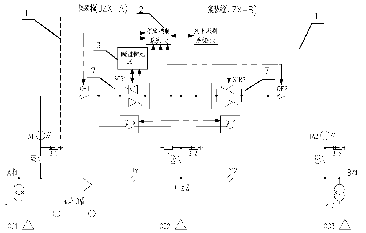
[0035] like figure 1As shown in the figure, the ground automatic phase separation device in this embodiment includes a train identification unit for identifying the running position and direction of the train, a logic control system 2 (LK), a valve control unit 3, and two thyristor valve groups 7 (SCR1, SCR2) The thyristor valve group unit formed in series and the current detection unit for detecting the current of the thyristor valve group 7, the thyristor valve group unit is respectively connected with the two-phase (A, B-phase) power supply arm of the catenary and the neutral area, and the logic control system 2 is based on The train running position and direction identified by the train identification unit are connected to a thyristor valve group 7 to supply p...


PUM


Abstract

The invention discloses a ground automatic neutral-section passing device and a control method thereof. The ground automatic neutral-section passing device comprises a train identification unit, a logic control system, a valve control unit, a thyristor valve block unit consisting of two thyristor valve blocks connected in series, and a current detection unit for detecting the current of the thyristor valve blocks, which are connected successively, wherein the thyristor valve block unit is connected with a two-phase power supply arm and a neutral zone of a catenary respectively; the logic control system is connected to one of the thyristor valve blocks according to an identified train travelling position and direction control to supply power for the neutral zone; and when phase change is needed, the logic control system is connected to the other thyristor valve block according to the state switching of thyristor current. According to the control method, neutral-section passing is realized through controlling the two thyristor valve blocks, and when the phase change is performed, if the current of one of the thyristor valve blocks achieves a cross-zero state through detection and judgment, the other thyristor valve block is opened immediately. The ground automatic neutral-section passing device and the control method disclosed by the invention have the advantages of being capable of realizing automatic neutral-section passing of a train under a condition that the power is not cut off, high in reliability, stable in operation, extremely small in power-off dead zone of the neutral zone, and the like.

Description

technical field [0001] The invention relates to the technical field of train over-phase, in particular to a ground automatic over-phase device and a control method thereof. Background technique [0002] my country's electrified railway traction power supply system adopts 27.5kV single-phase power supply mode. The traction substation converts the 110kV or 220kV three-phase power provided by the power system into 27.5kV single-phase AC power for the traction power supply network, but the single-phase power supply is easy to be in the power grid. Negative sequence current is generated in the grid, and the negative sequence current will have a great impact on the equipment, transmission lines, relay protection, etc. in the power grid. In order to balance the three-phase currents of A, B, and C in the power system, the traction substation implements a commutation and alternating power supply mode for the catenary; in order to prevent short-circuit between phases, the catenary is s...

Claims


Application Information

Patent Timeline
Patent Type & Authority Patents(China)
IPC IPC(8): B60M3/04
CPCB60M3/04
Inventor 周靖吴明水吕顺凯邱文俊周方圆刘永丽曹洋罗仁俊王才孝高原胡前龙礼兰熊强朱建波龚芬张典邓明
Owner ZHUZHOU NAT ENG RES CENT OF CONVERTERS
Why Eureka
Try Eureka