Windshield glass peripheral structure
A windshield and peripheral technology, applied in the direction of windshield, upper structure, upper structure sub-assembly, etc., can solve the problems of increased number of parts, assembly process or cost of parts, etc., and achieve the effect of inhibiting water immersion
- Summary
- Abstract
- Description
- Claims
- Application Information
AI Technical Summary
Problems solved by technology
Method used
Image

Examples
no. 1 approach
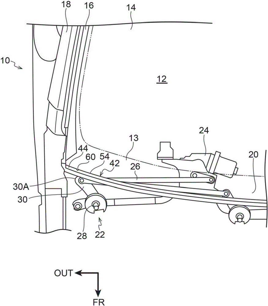
[0033] Below, use Figure 1 to Figure 5 A first embodiment of the peripheral structure of the windshield according to the present invention will be described. In addition, arrow FR appropriately shown in these figures indicates the vehicle front side, arrow UP indicates the vehicle upper side, and arrow OUT indicates the vehicle width direction outer side.
[0034] Such as figure 1 As shown, a windshield 14 is provided at the vehicle front side of the cabin 12 of the vehicle 10 . The upper end (not shown) of the windshield 14 is supported by a roof extending in the vehicle width direction and the vehicle front-rear direction, and the left and right ends 16 of the windshield 14 are supported by a pair of left and right front pillars 18 . Furthermore, the lower end portion 20 of the windshield 14 is supported by a not-shown dash panel, and the dash panel is connected to the dash panel via the dash inner panel. The lower end portion 20 of the windshield 14 is curved such that ...
no. 2 approach
[0050] Next, a second embodiment of the peripheral structure of the windshield according to the present invention will be described using FIG. 6 . In addition, about the structure and operation which are basically the same as those of 1st Embodiment, the same code|symbol as 1st Embodiment is attached|subjected, and the description and illustration are abbreviate|omitted in some cases.
[0051] Such as Figure 6A As shown, in this embodiment, the shape of the dehydration unit 80 is a semicircle. This semicircle is a circle centered on a point X which is the center of the dehydrating part upper end 82 in the vehicle width direction. In this embodiment, a gradual change portion 86 is also formed in which the width in the vehicle width direction is gradually narrowed from the upper end 82 of the dehydration portion to the lower end 82 of the dehydration portion, and the width in the vehicle width direction is set to be the narrowest at the lower end 88 of the dehydration portion....
no. 3 approach
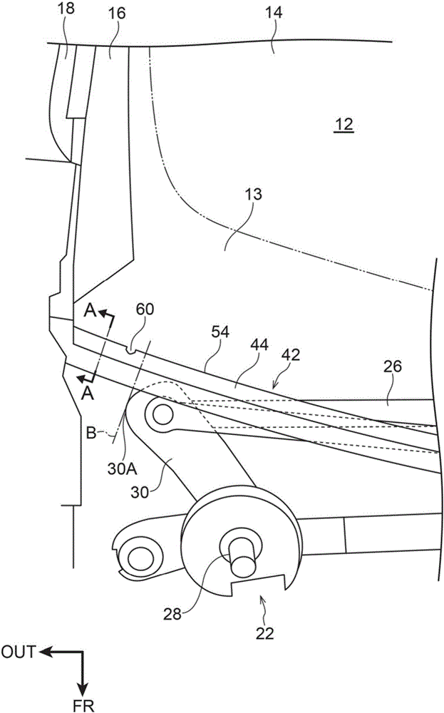
[0054] Next, use Figure 7 A third embodiment of the peripheral structure of the windshield according to the present invention will be described. In addition, about the structure and operation which are basically the same as those of 1st Embodiment, the code|symbol common to 1st Embodiment is attached|subjected, and the description and illustration are abbreviate|omitted in some cases.
[0055] Such as Figure 7 As shown, in this embodiment, the first dewatering unit 60 is provided on the outside of the line B in the vehicle width direction, and the second dewatering unit is provided on the outside of the first dewatering unit 60 in the vehicle width direction. 90 , the line B passes through the outermost point of the wiper unit 22 in the vehicle width direction and is perpendicular to the trim strip 42 . The interval between the first dehydration unit 60 and the second dehydration unit 90 is set to 20 to 30 mm.
[0056] In the present embodiment having the above-mentioned ...
PUM
 Abstract
Description
Claims
Application Information
 - R&D
- Intellectual Property
- Life Sciences
- Materials
- Tech Scout
- Unparalleled Data Quality
- Higher Quality Content
- 60% Fewer Hallucinations
Browse by: Latest US Patents, China's latest patents, Technical Efficacy Thesaurus, Application Domain, Technology Topic, Popular Technical Reports.
© 2025 PatSnap. All rights reserved.Legal|Privacy policy|Modern Slavery Act Transparency Statement|Sitemap|About US| Contact US: help@patsnap.com