Vertical lifting corrugation flange conveyor

A corrugated sidewall and conveyor technology, used in conveyors, conveyor objects, transportation and packaging, etc., can solve the problems of shortened life, large force on the tape, and more material scattering, so as to improve the life of the tape and prevent the The effect of material scattering and power consumption reduction

Active Publication Date: 2017-02-15
中铁隧道局集团有限公司勘察设计研究院 +1
View PDF12 Cites 13 Cited by
  • Summary
  • Abstract
  • Description
  • Claims
  • Application Information

AI Technical Summary

Problems solved by technology

At present, the corrugated sidewall conveyors at home and abroad are generally large-inclination corrugated sidewall belt conveyors, and there is no vertical lifting corrugated sidewall conveyor. This is mainly because: 1: Due to the angle of the corrugated sidewall belt The design is unreasonable. The corrugated sidewall conveyor transports less materials when it is vertically lifted, and most of the materials are easy to scatter to the ground, so the transmission efficiency is low, the power consumption per unit weight is large, and the cost is high. ; Two: In the case of vertical lifting, the angle between the tail bracket, the head bracket and the vertical truss is 90 degrees, and the corrugated sidewall belt is too sharp due to the corner, and the contact surface of the belt roller and the belt roller is relatively small. The belt is small, so that the local force on the belt is relatively large, it is easy to damage the belt prematurely, the service life is reduced, and there are more materials scattered at the corner; 3. Since there is no anti-sprinkling device, the corrugated sidewall belt is in the process of lifting. More materials are scattered, resulting in low conveying efficiency

Method used


Image

  • Vertical lifting corrugation flange conveyor
  • Vertical lifting corrugation flange conveyor

Examples


Embodiment Construction

[0014] The present invention is described in further detail below in conjunction with embodiment.

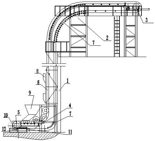
[0015] Such as figure 1 , 2 As shown, the vertical lifting corrugated sidewall conveyor of the present invention comprises a vertically arranged truss 1, a head support 2 arranged on the upper end of the truss 1 and an upper end reversing roller 3 arranged at the end of the head support, arranged on The tail support 4 under the truss 1 and the lower end reversing roller 5 arranged at the end of the tail support 4, the idlers provided on the tail support 4, truss 1, and head support 2 to provide support for the corrugated sidewall 6, Set in the tail support 4, the truss 1, the head support 2 and the corrugated edge band 6 that is wound around the upper end reversing drum 2 and the lower end reversing drum 5 and rotates up and down on the idler roller, the tail support 4, the head The upper support 2 is arranged horizontally and is perpendicular to the truss 1 respectively. Ther...


PUM


Abstract

The invention discloses a vertical lifting corrugation flange conveyor. The vertical lifting corrugation flange conveyor comprises a truss, a head support, an upper end redirection drum, a tail support, a lower end redirection drum and a corrugation flange belt which is arranged in the tail support, the truss and the head support and can do vertical rotation running; the tail support and the head support are horizontally arranged and are perpendicular to the truss, a concave-arc turn frame is arranged at the connecting position of the tail support and the truss, a convex-arc turn frame is arranged at the connecting position of the head support and the truss, encryption lifting rollers are arranged on the outer ring of the concave-arc turn frame and the inner ring of the convex-arc turn frame, the included angle between a transverse partition plate and a bottom plate of the corrugation flange belt is 75 degrees, a plurality of anti-scattering plates are arranged at the position, on the ascending side of the corrugation flange belt, of the truss and are bend plates, each anti-scattering plate at leas comprises an outer baffle, two side baffles and an inclined plate connected with the outer baffle and the two side baffles, and the inclined plates face the corrugation flange belt.

Description

technical field [0001] The invention relates to the technical field of bulk material conveying equipment, in particular to a vertical lifting corrugated sidewall conveyor. Background technique [0002] Corrugated sidewall conveyor is a kind of conveying equipment widely used in conveying bulk materials. At present, the corrugated sidewall conveyors at home and abroad are generally large-inclination corrugated sidewall belt conveyors, and there is no vertical lifting corrugated sidewall conveyor. This is mainly because: 1: Due to the angle of the corrugated sidewall belt The design is unreasonable. The corrugated sidewall conveyor transports less materials when it is vertically lifted, and most of the materials are easy to scatter to the ground, so the transmission efficiency is low, the power consumption per unit weight is large, and the cost is high. ; Two: In the case of vertical lifting, the angle between the tail bracket, the head bracket and the vertical truss is 90 de...

Claims


Application Information

Patent Timeline
Patent Type & Authority Applications(China)
IPC IPC(8): B65G23/44B65G39/12B65G15/58
CPCB65G15/58B65G23/44B65G39/12
Inventor 宋华牛思远王逢松杨陕南张彬陈小和陈小会
Owner 中铁隧道局集团有限公司勘察设计研究院
Why Eureka
Try Eureka