Power cable winding device

A winding device and a technology for power cables, which are applied in the directions of transportation and packaging, transportation of filamentous materials, and thin material handling, etc., can solve the problems of loose cable ends, easy disconnection, and influence on the firm winding of cables. , to achieve the effect of high compressive strength, high winding efficiency, and improved bearing pressure

Active Publication Date: 2017-02-15
STATE GRID SHANDONG ELECTRIC POWER CO LONGKOU POWER SUPPLY CO +1
View PDF17 Cites 3 Cited by
  • Summary
  • Abstract
  • Description
  • Claims
  • Application Information

AI Technical Summary

Problems solved by technology

The existing power cable winding tools directly bond the end of the cable to the reel, which is easy to disconnect and cause the end of the cable to loosen, affecting the firm winding of the cable

Method used


Image

  • Power cable winding device

Examples


Embodiment 1

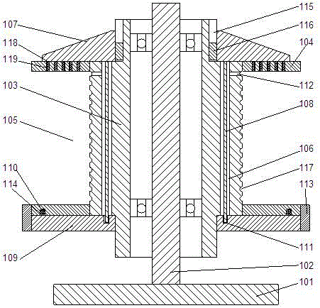
[0022] In this embodiment, in order to facilitate fixing the chassis, preferably, a bent portion 113 is provided on the outer edge of the baffle plate 104 near the side of the chassis 101, so that the bent portion is perpendicular to the side The baffle plate, the counterbore and the positioning hole 111 are all bar-shaped holes, and the outer end surface of the bottom cover 109 is screwed to the inner end surface of the bending portion 113 . When the bottom cover is screwed to the inside of the bending part, the cylindrical pin is clamped on the inside of the counterbore, and the end of the pressure rod away from the gland is inserted into the positioning hole, and the bottom cover is relatively fixed on the baffle by using the screw connection structure. At the same time, use the relatively fixed bottom cover to fix the end of the cable hooked on the pressure rod.

Embodiment 2

[0024] In this embodiment, on the basis of Embodiment 1, in order to improve the stability of the bottom cover, the cross-section of the cylindrical pin 110 has a T-shaped structure, and the inside of the counterbore is provided with a retaining edge 114 to make the counterbore A T-shaped slot is formed, and the cylindrical pin 110 can be inserted into the inner side of the retaining edge 114 . Use a T-shaped cylindrical pin to clamp the cylindrical pin inside the counterbore, then rotate the bottom cover relatively so that the cylindrical pin is clamped inside the retaining edge, and then use the cylindrical pin and the retaining edge to cooperate so that the bottom cover cannot move toward the The direction movement of the chassis can improve the stability of the bottom cover.

Embodiment 3

[0026] In the present invention, in order to facilitate the winding of cables inside the cavity, preferably, a wiring groove 117 is provided on the sleeve 103 inside the cavity 105, and the wiring groove 117 is arranged along the The outer wall of the casing 103 is helically arranged. When winding the cables, the innermost cables are wound in the wiring slots, which is conducive to the regular winding of the cables and makes the winding efficiency of the cables higher.


PUM


Abstract

The invention discloses a power cable winding device, which comprises a chassis and a middle shaft arranged in the middle of the chassis, a sleeve is arranged on the middle shaft, the sleeve is rotatably connected to the middle shaft through a bearing, the sleeve is provided with two check plates, a hollow cavity for winding a cable is formed between the two check plates, two symmetric through holes are arranged in the sleeve, an axis of the through holes is parallel with that of the sleeve, the outer side of one end of the sleeve away from the chassis is provided with a gland, the gland is provided with a press bar, and the press bar can be inserted into the inner sides of the through holes when the gland is attached to the end surfaces of sides of the check plates away from the chassis. The power cable winding device can fix the end part of the cable when winding of the power cable is facilitated, such that the winding of the power cable is more steady, and an integral structure is large in strength and not easy to damage.

Description

technical field [0001] The invention relates to a power cable winding device. Background technique [0002] During the winding process of the power cable, the end of the cable needs to be fixed to prevent it from being entangled and causing the cable to be confused. The existing power cable winding tool directly bonds the end of the cable to the reel, which is easy to disconnect, causing the end of the cable to loosen and affecting the firm winding of the cable. Contents of the invention [0003] The purpose of the present invention is to provide a power cable winding device, which can conveniently wind the power cable and at the same time fix the end of the power cable, so that the winding of the power cable is more stable, the overall structural strength is strong, and it is not easy to be damaged. [0004] The present invention is realized through the following technical solutions: [0005] A power cable winding device, comprising a chassis and a central shaft arrange...

Claims


Application Information

Patent Timeline
Patent Type & Authority Applications(China)
IPC IPC(8): B65H54/12B65H75/04B65H75/18
CPCB65H54/12B65H75/04B65H75/18
Inventor 王佳吴志军韩军吕刚
Owner STATE GRID SHANDONG ELECTRIC POWER CO LONGKOU POWER SUPPLY CO
Why Eureka
Try Eureka