
Compressor unit for a stretcher of a textile machine

A technology of drafting device and compaction unit, which is applied in spinning machines, drafting equipment, textiles and papermaking, etc., and can solve the problems of inaccurate positioning and movement of compacting components

Active Publication Date: 2017-02-15
MASCHINENFABRIK RIETER AG
View PDF8 Cites 5 Cited by
  • Summary
  • Abstract
  • Description
  • Claims
  • Application Information

AI Technical Summary

Problems solved by technology

The positioning and movement of the compaction elements can therefore only be done imprecisely

Method used


Image

  • Compressor unit for a stretcher of a textile machine
  • Compressor unit for a stretcher of a textile machine
  • Compressor unit for a stretcher of a textile machine

Examples


Embodiment Construction

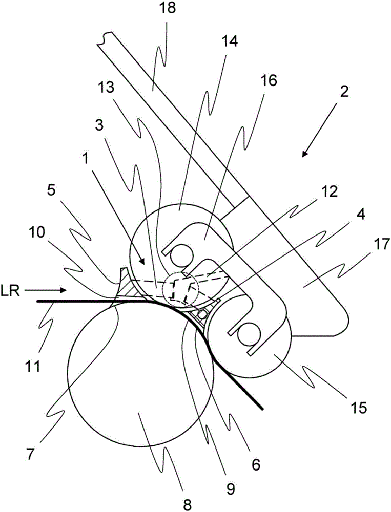
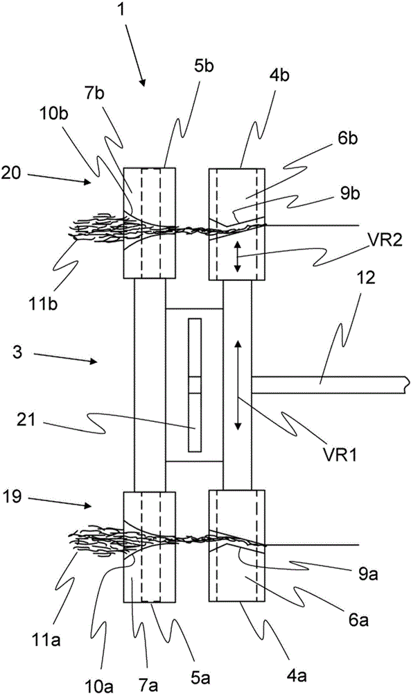
[0034] figure 1 A side sectional view of the compaction unit 1 in a part of the drafting device 2 is shown. The compacting unit comprises a holding part 3 on which a first guiding part 4 and, in this embodiment, an additionally provided second guiding part 5 are arranged. The guides 4 , 5 can be formed in one piece with the holder 3 . Furthermore, the first guide part 4 has a first contact surface 6 and the second guide part 5 has a second contact surface 7 . The two contact surfaces 6 , 7 are designed concavely. In particular, the two contact surfaces 6 , 7 are arranged to bear against the drafting roller 8 . A first compaction region 9 is arranged in and / or on the first guide part 4 and a second compaction region 10 is arranged in and / or on the second guide part 5 . Additionally or alternatively, the two compaction regions 9 , 10 can also be arranged in and / or on the respective contact surface 6 , 7 . The fiber strands 11 , which are guided in the conveying direction LR...


PUM


Abstract

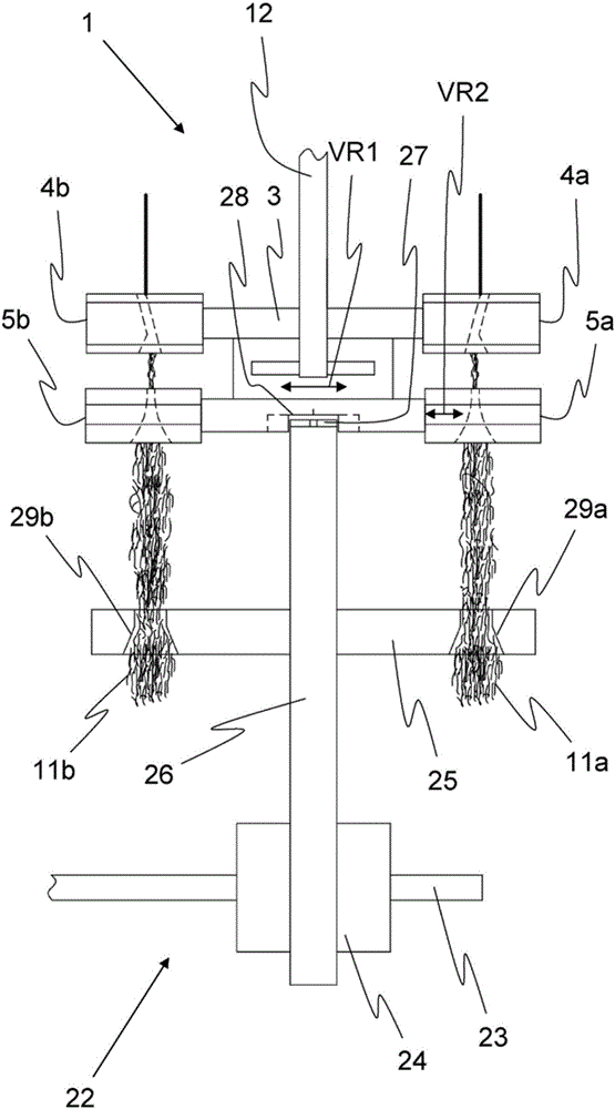
The invention relates to a compressor unit for a drafting machine (2) of a textile machine, comprising at least one guide (4a, 5a, 4b, 5b) and a support (3), wherein the at least one guide (4a, 5a, 4b, 5b) (6a, 7a, 6b, 7b) which rests against a drafting roller (8) during operation of the drafting unit (2), the holding device (3) Wherein a compaction area (9a, 10a, 9b, 10b) is arranged in and / or on the at least one guide (4a, 5a, 4b, 5b), in particular in and / or on the bearing surface (6a, 7a, 6b, 7b) (11a, 11b) guided by the compression region (9a, 10a, 9b, 10b), and having a receiving element (12) which has a connection (13) with the support (3), and Wherein the compressor unit (1) can be accommodated in the drafting unit (2) by means of the receiving element (12). According to the invention, the guide (4a, 5a, 4b, 5b) and / or the holder (3) and / or the receiving element (12) or the complete compressor unit (1) are displaceable in the axial direction of the drafting roller (8). In addition, the compressor unit (1) has an alignment area (28) in order to be able to align the compressor unit (1) on a traverse device.

Description

technical field [0001] The invention relates to a compacting unit for a drafting device of a textile machine. The compacting unit comprises at least one guide part and a holding part, wherein the at least one guide part is arranged on the holding part. The at least one guide has a contact surface which bears against the drafting device roller when the compacting unit is guided to the drafting device. A compaction region is provided in and / or on the at least one guide, in particular in and / or on the surface of the contact surface, so that the fiber strands guided by the compaction region are compacted. Furthermore, the compacting unit has a receiving part with a connection between the receiving part and the holder, and wherein the compacting unit can be accommodated in the drafting device by means of the receiving part. Background technique [0002] A drafting device for drafting fiber strands is known from EP 1953 275 B1. The drafting device comprises a mechanical device ...

Claims


Application Information

Patent Timeline
IPC IPC(8): D01H5/72D01H5/26
CPCD01H5/26D01H5/72
Inventor G·斯塔莱克K·胡贝尔
Owner MASCHINENFABRIK RIETER AG
Learn More