Light steel pitched roof substrate dry tile hanging structure and method for changing plane roof into pitched roof

A technology for sloping roofs and tile structures, applied to roof cladding, roofs, and roofs using tiles/slate tiles, etc., can solve problems such as poor seismic performance, unreliable tile connection methods, and greatly increased construction costs

Inactive Publication Date: 2017-02-15
浙江省二建建设集团有限公司
View PDF6 Cites 7 Cited by
  • Summary
  • Abstract
  • Description
  • Claims
  • Application Information

AI Technical Summary

Problems solved by technology

[0003] The conventional method is to add a layer of reinforced concrete structure to the slope roof on the basis of the original flat roof. The construction of the surface tile usually adopts two methods: dry laying and wet laying: the dry laying method means that the concrete has reached the design strength. Fix horizontal tile hanging strips on the sloping roof, and hook the tiles on the corresponding hanging tile strips from bottom to top, but the biggest drawback of this construction method is that each tile is hooked on the hanging tiles. If it is on the strip and is pressed by the tiles above, the connection method of the tiles is not reliable, and its anti-seismic performance is poor, and the tiles are easy to fall when encountering vibrations, strong

Method used


Image

  • Light steel pitched roof substrate dry tile hanging structure and method for changing plane roof into pitched roof
  • Light steel pitched roof substrate dry tile hanging structure and method for changing plane roof into pitched roof
  • Light steel pitched roof substrate dry tile hanging structure and method for changing plane roof into pitched roof

Examples


Embodiment Construction

[0026] The present invention will be further described below in conjunction with the accompanying drawings and specific embodiments.

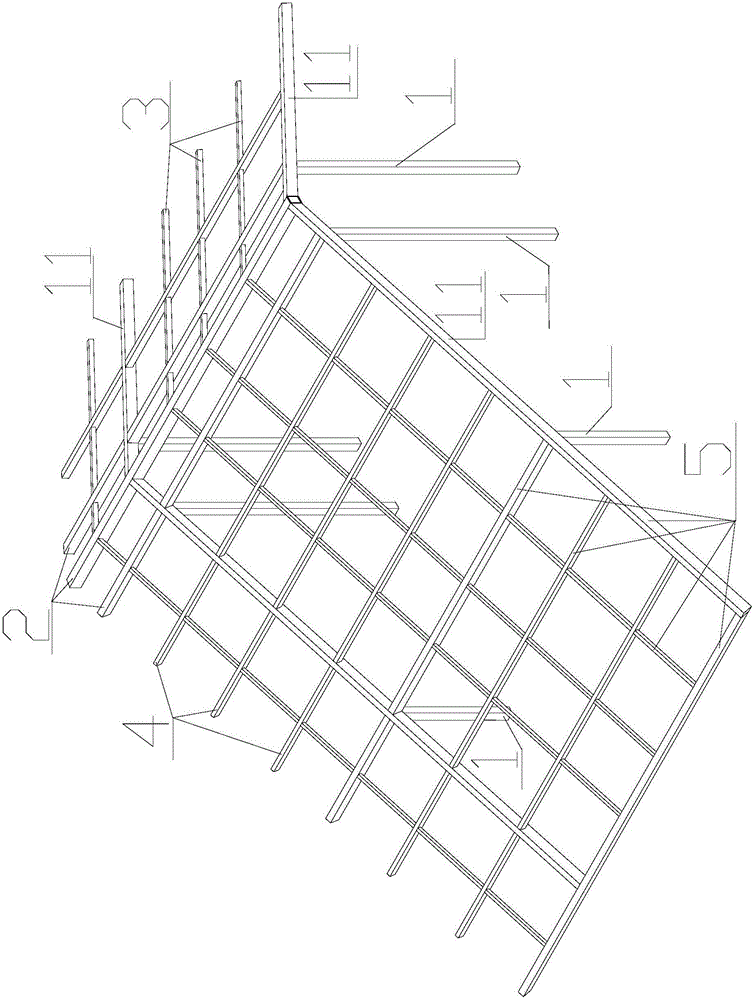
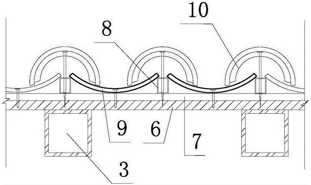
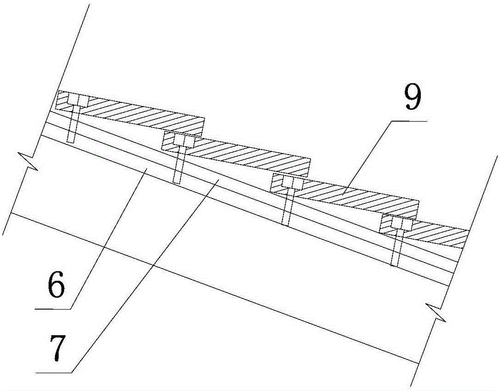
[0027] Such as figure 1 , figure 2 , image 3 , Figure 4 , Figure 5 , Image 6 As shown, the light steel sloping roof base dry-hanging tile structure of the present invention includes a light steel sloping roof base 5 composed of a horizontal main beam 2, an oblique main beam 11, a horizontal secondary beam 4 and an oblique connecting beam 3. And a plurality of columns supporting the base 5 of the light steel sloping roof. For the convenience of expression, first unify a concept, the horizontal direction refers to the direction parallel to the roof ridge, and the oblique direction refers to the direction perpendicular to the roof ridge, that is, the width direction of the roof. The upper surfaces of all the horizontal main beams 2, inclined main beams 11, inclined connecting beams 3, and horizontal secondary beams 4 on the same roof ar...


PUM


Abstract

The invention discloses a light steel pitched roof substrate dry tile hanging structure and a method for changing a plane roof into a pitched roof. The structure comprises a light steel pitched roof substrate and a plurality of stand columns. A board (6), a waterproof coil material (7) and counter battens (8) arranged on the light steel pitched roof substrate. A vertical column of cover tiles (10) are arranged on each counter batten (8). Each cover tile (10) is nailed to the board (6). The method is characterized in that each cover tile (10) is nailed to the board (6) through a self-tapping screw penetrating through a second preformed hole and the corresponding counter batten (8); an upper arc protruding strip (10.1) of each cover tile (10) is inserted into a clamping groove (12) of the last cover tile (10) in the same column; and the second preformed hole of an upper arc plate (10.2) of each cover tile (10) is covered by an arc main body (10.3) of the last cover tile (10) in the same column. According to the structure and method, the shock resistance is good, the construction period is short, and mounting is convenient.

Description

technical field [0001] The invention relates to building reconstruction and decoration construction technology in the field of civil engineering, in particular to a light steel sloping roof base dry hanging tile structure and a method for changing a flat roof to a sloping roof. Background technique [0002] In the process of new urbanization construction, ecological garden city and old city reconstruction in our country, it is often necessary to transform the flat roof of the building into a sloping roof. [0003] The conventional method is to add a layer of reinforced concrete structure to the slope roof on the basis of the original flat roof. The construction of the surface layer tiles usually adopts two methods: dry laying and wet laying: the dry laying method refers to that the concrete has reached the design strength. Fix the horizontal tile hanging strips on the sloping roof, and hook the tiles on the corresponding hanging tile strips from bottom to top, but the bigges...

Claims


Application Information

Patent Timeline
IPC IPC(8): E04B7/02E04D1/02E04D1/34E04D13/00E04D13/16E04G23/00E04B1/98
CPCE04B1/98E04B7/02E04D1/02E04D1/3402E04D13/00E04D13/16E04D2001/3426E04G23/00
Inventor 葛主强楼少敏程昉毛建光于鑫
Owner 浙江省二建建设集团有限公司
Why Eureka
Try Eureka