A sealing device for a micro rotor engine

A rotary engine and sealing device technology, which is applied to the sealing device of the engine, the engine components, the machine/engine, etc., can solve the problems of complex structure and easy failure of the sealing device for the rotary engine, so as to improve the power and life, work reliably, Improve the effect of partial wear

Active Publication Date: 2019-05-03
BEIJING INSTITUTE OF TECHNOLOGYGY
View PDF8 Cites 0 Cited by
  • Summary
  • Abstract
  • Description
  • Claims
  • Application Information

AI Technical Summary

Problems solved by technology

[0004] Aiming at the problem of complex structure and easy failure of the sealing device for rotor engines in the prior art, the present invention discloses a sealing device for micro-rotor engines. The technical problem to be solved is to provide a sealing device for micro rotor engines with a reasonable The sealing device of the small rotor engine reduces the wear of the sealing plate, improves the eccentric wear of the sealing plate during the working process, improves the power and life of the micro rotor engine, and is easy to install

Method used


Image

  • A sealing device for a micro rotor engine
  • A sealing device for a micro rotor engine
  • A sealing device for a micro rotor engine

Examples


Embodiment 1

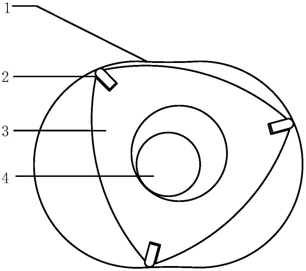
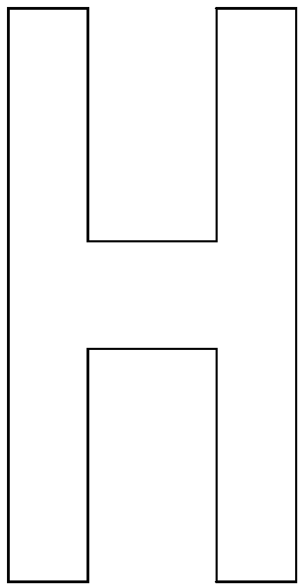
[0027] This embodiment discloses a sealing device for a micro-rotary engine, such as figure 1 shown. Taking a 5CC rotor engine with a radius of 21mm, an eccentricity of 3mm and a thickness of 14.5mm as an example, the sealing sheet 2 and the spring sheet 5 are installed in the sealing groove on the rotor. figure 2 and image 3 Respectively, the front view and the left view of the leaf spring. Figure 4 , Figure 5 and Figure 6 It is a top view, a front view and a rear view of the sealing sheet 2. The sealing sheet 2 and the spring sheet 5 are installed in the sealing groove on the rotor, wherein the arc portion of the top of the sealing sheet 2 is in contact with the cylinder 1 . The spring piece 5 is installed on the spring piece on the back of the sealing piece 2, and its arc top is in contact with the bottom of the sealing groove. The two bosses on the back of the sealing piece 2 can prevent the movement of the spring piece 5 and have a certain pre-tightening force. ...


PUM


Abstract

The invention discloses a sealing device used for a micro-miniature rotor engine, relates to a sealing device used for a micro-miniature rotor engine and adopting a combined type of leaf springs and sealing pieces and belongs to the field of micro-miniature rotor engines. The sealing device comprises the sealing pieces and the leaf springs; each leaf spring is in a shape of an arc; and the middle portions of the two ends in the up-down direction are provided with grooves used for being in clearance fit with rib plates. The top end of each sealing piece is in a shape of an arc; the middle portion of each sealing piece is rectangular; the upper end and the lower end of the back portion of each sealing piece are provided with convex tables preventing the leaf springs from moving; and the rib plates reducing the gas leakage area are machined in the middles of the back portions of the sealing pieces. The rib plates are in clearance fit with the grooves formed in the end portions of the leaf springs, and the grooves in the upper sides and the lower sides of the leaf springs can stride cross the two sides of each rib plate. During installation, the back portions of the leaf springs make contact with the portions of the bottoms of rotor sealing grooves, and the tops of the sealing pieces make contact with the inner wall of a cylinder. By means of the sealing device, the abrasion amount of the sealing pieces can be reduced, eccentric abrasion of the sealing pieces in the working process can be improved, the power and the service life of the micro-miniature rotor engine are improved, and installing is convenient.

Description

technical field [0001] The invention relates to a sealing device for a micro-rotor engine, in particular to a sealing device for a micro-rotor engine in the form of a combination of a spring plate and a sealing plate, and belongs to the field of a micro-rotor engine. Background technique [0002] With the development of micro-electro-mechanical systems (MEMS), the development of micro-energy systems with small volume, light weight, high energy density, and continuous operation has become the focus of attention in various countries. Compared with conventional power supply equipment, micro-engines use hydrocarbons as fuels, and their energy density is higher than that of battery systems. Due to the development of fuel diversification, they also have the potential for low cost. Therefore, micro-engines will have a wide range of application prospects in electronic devices in various industries such as industry, agriculture, environmental protection, and medical care. [0003] T...

Claims


Application Information

Patent Timeline
Patent Type & Authority Patents(China)
IPC IPC(8): F02F11/00
CPCF02F11/007
Inventor 刘金祥张帅左正兴张岩
Owner BEIJING INSTITUTE OF TECHNOLOGYGY
Why Eureka
Try Eureka