Impeller of centrifugal fan
A centrifugal fan and impeller technology, applied in mechanical equipment, machines/engines, liquid fuel engines, etc., can solve the problems of high noise and low efficiency, and achieve the effects of high efficiency, increased distance, and excellent aerodynamics
Active Publication Date: 2017-02-15
ZHUZHOU ELECTRIC LOCOMOTIVE CO
View PDF11 Cites 14 Cited by
- Summary
- Abstract
- Description
- Claims
- Application Information
AI Technical Summary
Problems solved by technology
[0003] The technical problem to be solved by the present invention is to provide a bionic noise reduction, excellent aerodynamics, and high efficiency for the problems of "jet-wake" phenomenon formed at the outlet of the impeller during the operation of the existing centrifugal fan, resulting in high noise and low efficiency. High centrifugal fan bionic impeller
Method used
View moreImage
Smart ImageViewing Examples

Examples
Embodiment Construction
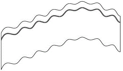
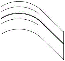
[0010] The following will refer to Figure 1-Figure 3 The structure of the present invention will be described.
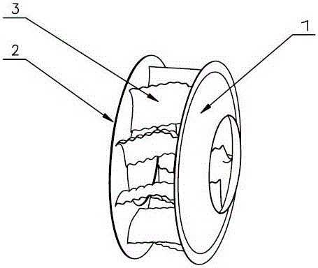
[0011] see figure 1 , the centrifugal fan bionic impeller of the present invention includes a front ring 1 and a rear ring 2, a plurality of blades 3 are fixed between the front ring 1 and the rear ring 2, and the blades 3 are fixed together with the front ring 1 and the rear ring 2 by welding .
[0012] see figure 2 , image 3 , the longitudinal section of the blade 3 is wavy, and the transverse section is arc-shaped, effectively imitating the shape of the dorsal fin and shell of the humpback whale.
Login to View More PUM
 Abstract
The invention discloses an impeller of a centrifugal fan. The impeller of the centrifugal fan comprises a front coil (1) and a back coil (2). A plurality of blades (3) are welded and fixed between the front coil and the back coil, vertical fracture surfaces of the blades are undulate, and horizontal fracture surface are circular-arc-shaped. The vertical fracture surfaces of the blades simulate the shell shape of a humpback and the horizontal fracture surfaces of the blades simulate the dorsal fin shape of the humpback. The eddy separation position at outlets of the blades is changed, the distance between eddy centers is enlarged, and the disturbance of eddy separation to flow is restrained, so that aerodynamic noise is reduced. The impeller of the centrifugal fan has the advantages of bionic noise reduction, good aerodynamics, high efficiency and the like.
Description
technical field [0001] The invention relates to a centrifugal fan, in particular to a centrifugal fan impeller. Background technique [0002] The centrifugal fan is widely used, and the impeller is an important component of the centrifugal fan. The rotation of the impeller drives the gas flow, and whether its structure is reasonable directly affects the overall performance of the fan. At present, the blades of centrifugal fan impellers in China are generally straight blades. Although the workmanship is simple, the phenomenon of "jet-wake" is easily formed at the outlet of the impeller during the operation of the fan, resulting in high noise and low efficiency. Contents of the invention [0003] The technical problem to be solved by the present invention is to provide a bionic noise reduction, excellent aerodynamics, and high efficiency for the problems of "jet-wake" phenomenon formed at the outlet of the impeller during the operation of the existing centrifugal fan, result...
Claims
Login to View More Application Information
Patent Timeline
 IPC IPC(8): F04D29/30F04D29/66
CPCF04D29/30F04D29/667F05D2240/301
Inventor 李行肖云华刘洋余陈邵银玲
Owner ZHUZHOU ELECTRIC LOCOMOTIVE CO