Defrosting control system

A control system and filter technology, used in refrigerators, refrigeration components, refrigeration and liquefaction, etc., can solve the problems of liquid refrigerant higher than the storage temperature, compressor damage, compressor oil throwing wear and other problems

Inactive Publication Date: 2017-02-15
广州冰泉制冷设备有限责任公司
View PDF9 Cites 1 Cited by
  • Summary
  • Abstract
  • Description
  • Claims
  • Application Information

AI Technical Summary

Problems solved by technology

The gaseous refrigerant turns into a liquid refrigerant with a lower temperature and returns to the compressor after being evaporated by the condenser. The machine continuously sucks air, and a large amount of gas-liquid mixed refri

Method used


Image

  • Defrosting control system
  • Defrosting control system

Examples


Embodiment Construction

[0018] Below in conjunction with accompanying drawing, invention is described in further detail.

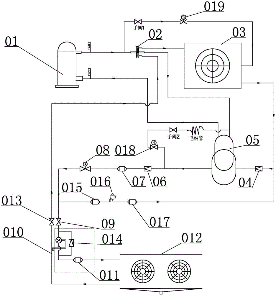
[0019] Such as Figure 1-2As shown, a defrosting control system includes a compressor 01, a four-way valve 02 communicated with the compressor 01, a condenser 03 communicated with the four-way valve 02, a first one-way valve 04 communicated with the condenser 03, The gas-liquid separator 05 communicated with the first one-way valve 04 and the compressor 01, the second one-way valve 06 communicated with the gas-liquid separator 05, the first filter 07 communicated with the second one-way valve 06, The electromagnetic valve 08 communicated with the first filter 07, the first threaded interface 09 communicated with the electromagnetic valve 08, the thermal expansion valve 010 communicated with the first threaded interface 09, the second filter 011 communicated with the thermal expansion valve 010, The air cooler 012 communicated with the second filter 011, the second threaded inter...


PUM


Abstract

The invention discloses a defrosting control system comprising a compressor, a four-way valve communicating with the compressor, a condenser, a first one-way valve, a gas-liquid separator, a second one-way valve, a first filter, an electromagnetic valve, a first threaded coupling, a thermal expansion valve, a second filter, an air cooler, a second threaded coupling, a third one-way valve, a third filter, an electronic expansion valve and a fourth filter. The gas-liquid separator communicates with the four-way valve, and the fourth filter communicates with the condenser. The defrosting control system has the effects of enhancing the protection for the compressor and avoiding a liquid impact phenomenon.

Description

technical field [0001] The invention relates to a defrosting control system applied in a refrigerator. Background technique [0002] At present, the refrigeration and defrosting systems used in ice storage are prone to liquid shock during the start-up process of the compressor when the hot gas defrosting system turns to refrigeration. Because in the process of defrosting, the functions of the cooling fan and the condenser are interchanged, which is equivalent to a heat pump system, but the temperature is lower than that of the heat pump. When defrosting, the high-temperature and high-pressure gaseous refrigerant is continuously passed into the air cooler through the compressor, so that the temperature of the air cooler coil is raised, thereby melting the frost on the surface of the coil to achieve the defrosting effect. The gaseous refrigerant turns into a liquid refrigerant with a lower temperature and returns to the compressor after being evaporated by the condenser. The...

Claims


Application Information

Patent Timeline
IPC IPC(8): F25B41/04F25B47/02F25B49/02F25B41/06F25B41/20F25B41/31
CPCF25B47/022F25B49/022F25B41/37F25B41/20Y02B30/70Y02B40/00
Inventor 冯昊艳杨红波龚千吴会娟陈广超叶周平吕定新周学荣罗立勃曾庆龙王剑平
Owner 广州冰泉制冷设备有限责任公司
Why Eureka
Try Eureka