Dynamic sealing device for inner side of bottom of cooling bed trolley and sealing method of dynamic sealing device

A technology of dynamic sealing and trolley, which is applied in the direction of furnace type, furnace, lighting and heating equipment, etc., can solve the problems of poor sealing effect, achieve the effects of reducing power consumption, increasing hot air temperature, and increasing boiler power generation

Active Publication Date: 2017-02-15
ANHUI UNIVERSITY OF TECHNOLOGY
View PDF8 Cites 0 Cited by
  • Summary
  • Abstract
  • Description
  • Claims
  • Application Information

AI Technical Summary

Problems solved by technology

[0006] The purpose of the present invention is to overcome the problem of poor sealing effect between the existing cooling bed trolley and the bottom static beam, and provide a dynamic sealing device and sealing method for the inner side of the bottom of the cooling bed trolley, w

Method used


Image

  • Dynamic sealing device for inner side of bottom of cooling bed trolley and sealing method of dynamic sealing device
  • Dynamic sealing device for inner side of bottom of cooling bed trolley and sealing method of dynamic sealing device
  • Dynamic sealing device for inner side of bottom of cooling bed trolley and sealing method of dynamic sealing device

Examples


Embodiment 1

[0037] The dynamic sealing device inside the bottom of the cooling bed trolley in this embodiment is designed to solve the problems that the sealing rubber plate used at the bottom of the cooling bed trolley of the existing belt type sintering machine is easy to age, has a short life, poor elastic deformation, and hot air leakage. Developed.

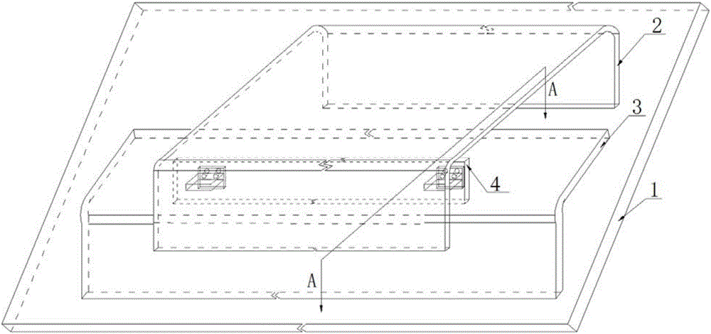
[0038] refer to figure 1 , the dynamic sealing device inside the bottom of the cooling bed trolley in this embodiment includes the cooling bed trolley, the upper connecting piece 2, the lower connecting piece 3 and the sealing piece 4, and the wheels on the cooling bed trolley pass through it relative to the static beam below 1 swipe. Both sides of the bottom of the cooling bed trolley (here, "both sides of the bottom of the cooling bed trolley" refers to the left and right sides of the sliding direction of the cooling bed trolley. It should be noted that, figure 1 Only the structure on one side of the bottom of the cooling bed trolley...

Embodiment 2

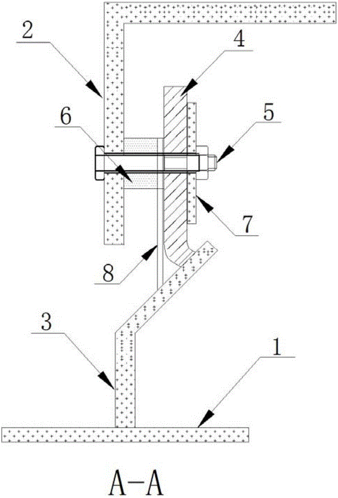
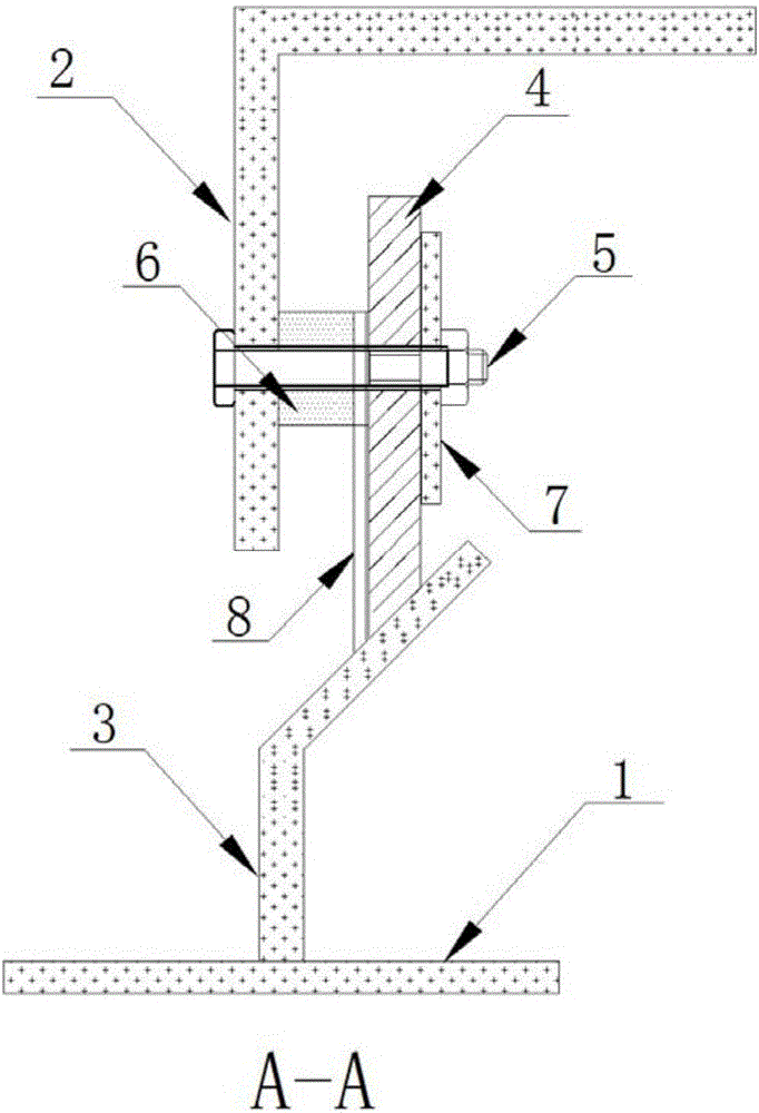
[0040] The structure of the inner dynamic sealing device at the bottom of the cooling bed trolley in this embodiment is basically the same as that in Embodiment 1. Further: in this embodiment, the lower connecting part 3 includes an upper inclined plate and a lower connecting plate, and the lower connecting plate is vertically fixed On the static beam 1, the upper inclined plate is fixedly connected to the upper end of the lower connecting plate and the angle between the upper inclined plate and the lower connecting plate is maintained at 105° to 165° (165° is used in this embodiment), and the lower end of the sealing member 4 is on the lower end of the lower connecting plate. the upper surface of the connecting plate.

[0041] In this embodiment, the angle between the upper inclined plate and the lower connecting plate is maintained at 105° to 165°, so that the contact area between the lower end of the sealing member 4 and the upper surface of the lower connecting member is incr...

Embodiment 3

[0043] The structure of the dynamic sealing device inside the bottom of the cooling bed trolley in this embodiment is basically the same as that in Embodiment 2, further:

[0044] refer to Figure 4~5 , the seal 4 includes two layers of steel brushes 4-1, and the steel brush welding points 4-4 provided around the two layers of steel brushes 4-1 (that is, the two layers of steel brushes 4-1 are welded on the outside by welding) Welding and fixing together) are fixed together, and a heat-resistant interlayer 4-2 is sandwiched between the two layers of steel brushes 4-1 (in this specific embodiment, the heat-resistant interlayer 4-2 can be a high-temperature-resistant ceramic cloth), which is used to reduce The air leakage rate in the direction perpendicular to the side of the steel brush 4-1 is small, and the sealing performance of the sealing member 4 is strengthened. refer to figure 2 and 4 , the seal 4 is provided with a bolt hole 4-3, the bolt 5 passes through the bolt h...


PUM


Abstract

The invention discloses a dynamic sealing device for the inner side of the bottom of a cooling bed trolley and a sealing method of the dynamic sealing device and relates to a sealing device of a cooling bed trolley on a sintering machine. The dynamic sealing device for the inner side of the bottom of the cooling bed trolley and the sealing method of the dynamic sealing device aim at overcoming the defect that the sealing effect between an existing cooling bed trolley and a bottom static beam is poor. The dynamic sealing device comprises the cooling bed trolley, upper connecting parts, lower connecting parts and sealing parts. The cooling bed trolley slides relative to a lower static beam through wheels on the cooling bed trolley; the upper connecting parts are arranged on the two sides of the bottom of the cooling bed trolley correspondingly, and the lower connecting parts are arranged at the positions, corresponding to the lower portions of the upper connecting parts, on the static beam. The inner side walls of the upper connecting parts are provided with the sealing parts with the lower ends abutting against the lower connecting parts. Each sealing part comprises at least one layer of steel brush. The dynamic sealing device for the inner side of the bottom of the cooling bed trolley and the sealing method of the dynamic sealing device well solve the problem that the sealing effect between the cooling bed trolley and the bottom static beam is poor.

Description

technical field [0001] The invention relates to a sealing device for a cooling bed trolley on a sintering machine, and more specifically relates to a dynamic sealing device and a sealing method for the bottom inner side of a cooling bed trolley. Background technique [0002] In iron and steel production, sintering waste heat recovery is one of the major energy-saving links. However, in the prior art, rubber plates are mainly used to seal between the cooling bed trolley and the bottom static beam of the sintering machine. After long-term operation, the rubber plates are easy to age and fall off. The service life is short, and replacement is difficult. The air leakage rate is even as high as 50%, and the power generation of the waste heat boiler is less than half of the design value. Therefore, reducing the air leakage rate of the cooling bed trolley has become one of the technical bottlenecks of sintering production. After the on-site investigation of the structure of the exi...

Claims


Application Information

Patent Timeline
IPC IPC(8): F27B21/08F27D99/00
CPCF27B21/00F27D99/0073
Inventor 陈光王恒达包向军王情伟查承志
Owner ANHUI UNIVERSITY OF TECHNOLOGY
Why Eureka
Try Eureka