
A composite material flexible part assembling deviation analysis method

A technology of composite materials and flexible parts, applied in special data processing applications, instruments, electrical digital data processing, etc.

Inactive Publication Date: 2017-02-15
NANJING UNIV OF AERONAUTICS & ASTRONAUTICS
View PDF6 Cites 9 Cited by
  • Summary
  • Abstract
  • Description
  • Claims
  • Application Information

AI Technical Summary

Problems solved by technology

[0007] The purpose of the present invention is to solve the problem that the assembly deviation exceeds the limit due to the lack of consideration of the layering angle error of the composite material flexible part in the analysis of the assembly deviation of the existing flexible parts. Under the premise of small angle error, a method for composite material parts is proposed At the same time, it is a practical composite material flexible part assembly deviation analysis method that considers the force change of the part passing the positioning point during the compression and release process in the flexible part assembly deviation analysis, so that the deviation prediction of the composite flexible part assembly is more accurate and more in line with engineering actual

Method used


Image

  • A composite material flexible part assembling deviation analysis method
  • A composite material flexible part assembling deviation analysis method
  • A composite material flexible part assembling deviation analysis method

Examples


Embodiment Construction

[0041] The present invention will be further described below in conjunction with the accompanying drawings and specific embodiments.

[0042] like Figure 8 shown.

[0043] A method for analyzing assembly deviation of composite material flexible parts, which includes the following steps:

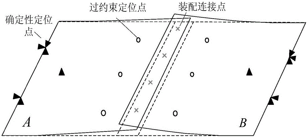
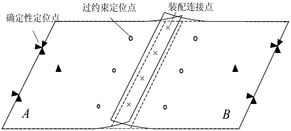
[0044] (1) Collect data to obtain the initial manufacturing deviation of composite flexible parts A and B and alpha 1 、α 2 、α 3 ,...,α n , β 1 , β 2 , β 3 ,...,β m ;in Respectively represent the manufacturing deviation of parts A and B passing through the constraint positioning point; represent the manufacturing deviation at the assembly connection points of composite flexible parts A and B respectively; α 1 ~α n and beta 1 ~β m Indicates the actual laying angle error of each layer of composite flexible parts A and B, that is, the difference from the nominal angle, where the subscripts m and n represent the number of layers of composite flexible parts A and B respectively; ...


PUM


Abstract

The invention provides a composite material flexible part assembling deviation analysis method. The method comprises the steps of: 1, collecting data and obtaining initial manufacture deviations of composite material flexible parts; 2, extracting corresponding super-element rigidity matrixes by using finite element software; 3, establishing a part rigidity matrix model based on fiber reinforced composite material lay-up angle deviations and defining super-element rigidity matrixes; 4, performing determinative location on the flexible parts based on rigid body models; 5, adding an over-location clamp; 6, clamping assembling connecting points of the composite material flexible parts to nominal positions via assembling pressing force; 7, forming an assembling body when the composite material flexible parts arrive at the nominal assembling positions by the action of the assembling pressing force; 8, determining a rebound deviation; 9, finally releasing the over-location clamp to obtain a rebound deformation deviation, and obtaining the final rebound deviation of the assembling body. The method can determine the influence of composite material lay-up angle deviations on flexible assembling body deviations and thus improve the engineering application scientificity.

Description

technical field [0001] The invention relates to a composite material technology, in particular to a composite material flexible part assembly size deviation prediction technology, in particular to a composite material flexible part assembly deviation analysis method considering the composite material layup angle error. [0002] technical background [0003] Nowadays, as an advanced material, fiber-reinforced composite materials are becoming more and more popular in the manufacturing industry due to their advantages such as high specific strength and specific stiffness. Compared with traditional metal parts, composite parts often have better mechanical properties while greatly reducing weight. The layering of fiber-reinforced composite materials in the manufacturing process will directly determine the performance of the material, and due to the characteristics of its manufacturing process and the particularity of the shape of the parts, there will inevitably be deviations in t...

Claims


Application Information

Patent Timeline
IPC IPC(8): G06F17/50
CPCG06F30/23G06F2111/10
Inventor 王志国王焱张玮刘霞张永健苏成阳
Owner NANJING UNIV OF AERONAUTICS & ASTRONAUTICS
Learn More