
New energy automobile or charging gun large current connector waterproof structure

A technology for high-current connectors and new energy vehicles. It is applied in the direction of vehicle connectors, connections, and parts of connection devices. It can solve problems such as short-circuit and leakage accidents, short-circuit and leakage, and unreliable sealing of high-current connectors. Achieve the effects of avoiding short circuit and leakage accidents and high sealing reliability

Inactive Publication Date: 2017-02-15
SAIYANG ELECTROMECHANICAL
View PDF5 Cites 11 Cited by
  • Summary
  • Abstract
  • Description
  • Claims
  • Application Information

AI Technical Summary

Problems solved by technology

When the existing high-current connector is used, the socket is installed in the plug, and the joint between the socket and the plug is provided with a sealing structure, so that the socket and the plug are in a sealed state after being combined, but after the socket and the plug are separated, due to the contact between the terminals of the socket and the plug There is no sealing structure between the insulating bases and between the insulating base and the plug shell. Therefore, it is inevitable that water or oil will enter the socket and plug during production, transportation, and maintenance, and then penetrate into the battery, electric control, and motor. or inside the connector, causing short circuit and leakage accidents, especially when the charging pile is exposed outdoors, water is more likely to pass through the socket and plug to cause short circuit and leakage accidents. Cause short circuit and leakage accident

Method used


Image

  • New energy automobile or charging gun large current connector waterproof structure
  • New energy automobile or charging gun large current connector waterproof structure
  • New energy automobile or charging gun large current connector waterproof structure

Examples


Embodiment Construction

[0019] The present invention will be further described below according to the accompanying drawings and in conjunction with the embodiments.

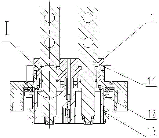
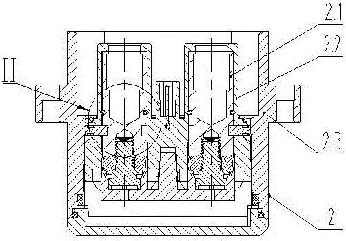
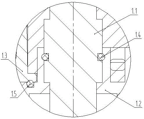
[0020] The waterproof structure of high-current connectors for new energy vehicles or charging guns shown in the attached drawings includes socket 1 and plug 2; socket 1 includes terminal I1.1, socket insulating seat body 1.2, and socket shell 1.3. In this embodiment, terminal I1 .1 is a male terminal (in other embodiments, terminal I1.1 is a female terminal); terminal I1.1 is inserted into the inner hole of the socket insulating seat body 1.2, and the socket insulating seat body 1.2 is inserted into the notch hole of the socket shell 1.3 Middle; the joint of the outer wall of the terminal I1.1 in the socket 1 and the inner hole of the socket insulating seat body 1.2 is provided with a sealing structure I1.4. In this embodiment, the sealing structure I1.4 is a radial sealing structure, and the sealing structure I1.4 Including sealing gr...


PUM


Abstract

The invention discloses a new energy automobile or charging gun large current connector waterproof structure. The structure comprises a socket and a plug; the socket comprises a terminal I, a socket insulating base body and a socket shell; the terminal I is a male terminal or a female terminal; the plug comprises a terminal II, a plug insulating base body, and a plug shell; the terminal II is the female terminal or the male terminal; the combining part of the outer wall of the terminal I in the socket and the inner hole of the socket insulating base body is provided with a sealing structure I; the combining part of the socket insulating base body and the socket shell is provided with a sealing structure II; the combining part of the outer wall of the terminal II in the plug and the inner hole of the plug insulating base body is provided with a sealing structure III; and the combining part of the plug insulating base body and the plug shell is provided with the sealing structure IV. Under the condition that the plug is not plugged in the socket, if liquid from the external is sputtered to the plugging surface of the plug or the socket, the liquid cannot permeate in the wiring (cable in soldering, compression joint or locking with copper medal) part of the plug or the socket.

Description

technical field [0001] The invention relates to a waterproof structure for electrical appliances, in particular to a waterproof structure for a high-current connector of a new energy vehicle or a charging gun. Background technique [0002] The energy power part of the new energy electric vehicle is mainly composed of the battery pack, electric control, motor and external charging pile. Among these four components, the battery pack and charging pile, the electric control and battery pack, and the It is connected through a high-current connector (including a charging gun) and a wire; in addition, the charging gun is also connected through a high-current connector and a wire. Existing high-current connectors include sockets and plugs; sockets mainly include terminals (male or female), socket insulators, and socket shells; terminals (male or female) are installed in socket insulators, and socket insulators are installed in socket shells; plugs mainly include Terminal (male or f...

Claims


Application Information

Patent Timeline
Patent Type & Authority Applications(China)
IPC IPC(8): H01R13/52
CPCH01R13/5202H01R13/521H01R2201/26
Inventor 颜国兵
Owner SAIYANG ELECTROMECHANICAL
Learn More