Mismatch compensation method and mismatch compensation device for radio-frequency transmission line

A technology of radio frequency transmission and mismatch compensation, applied in the field of radio frequency, it can solve the problem of inconspicuous effect of the radio frequency transmission line, and achieve the effect of solving the mismatch

Active Publication Date: 2017-02-15
YULONG COMPUTER TELECOMM SCI (SHENZHEN) CO LTD
View PDF5 Cites 4 Cited by
  • Summary
  • Abstract
  • Description
  • Claims
  • Application Information

AI Technical Summary

Problems solved by technology

[0008] In this technical solution, by extracting the scattering parameters of the radio frequency transmission line in its working frequency band, and calculating the impedance value of the radio frequency transmission line that needs to be compensated according to the scattering parameters, and then determining the value of the open transmission line that needs to be added to the radio frequency transmission line based on the impedance value that needs to be compensated parameter, which makes it possible to compensate the m

Method used


Image

  • Mismatch compensation method and mismatch compensation device for radio-frequency transmission line
  • Mismatch compensation method and mismatch compensation device for radio-frequency transmission line
  • Mismatch compensation method and mismatch compensation device for radio-frequency transmission line

Examples


Embodiment approach 1

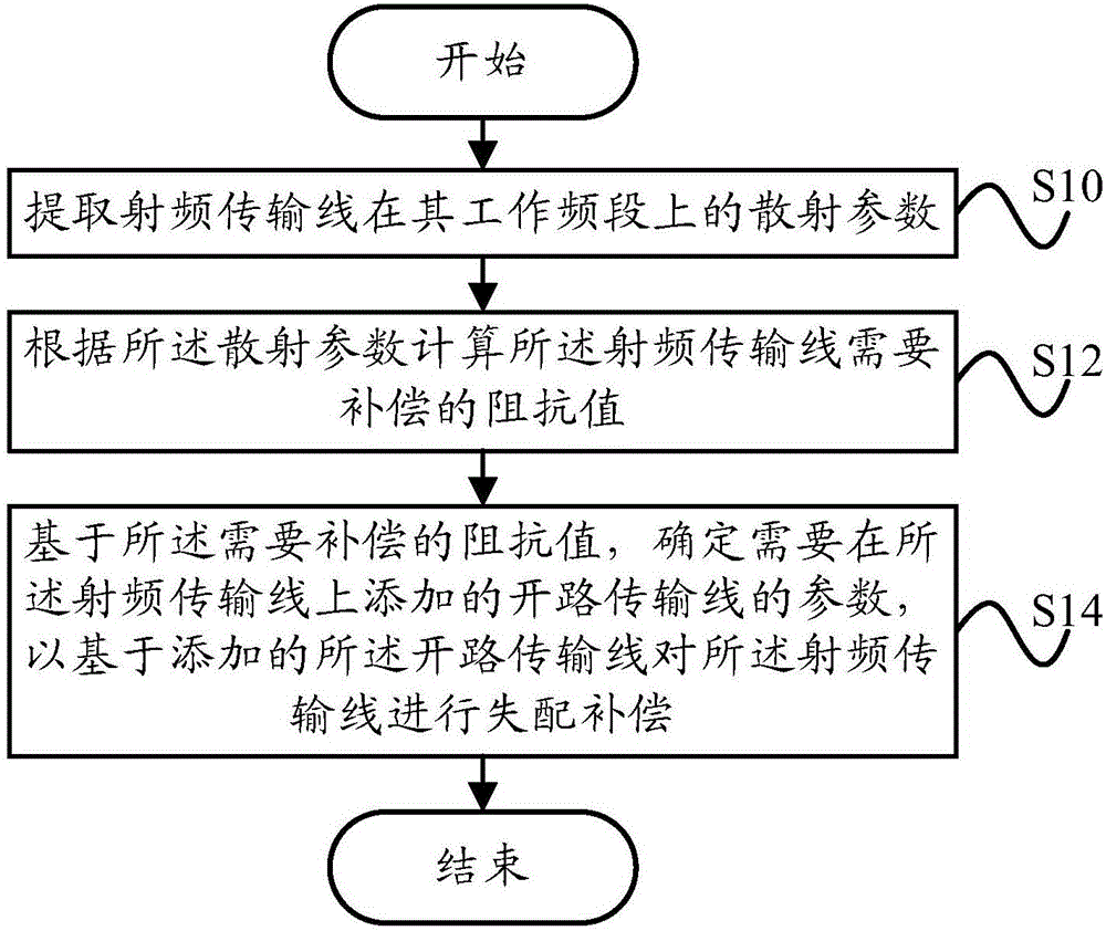
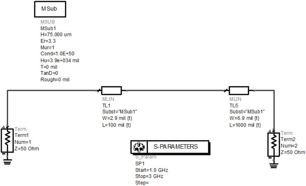
[0047] The scattering parameters of the radio frequency transmission line in its working frequency band are extracted from the circuit diagram where the radio frequency transmission line is located by means of software simulation. That is, the scattering parameters of the RF transmission line in its working frequency band can be directly extracted from the circuit diagram (such as the PCB circuit diagram) where the RF transmission line is located

Embodiment approach 2

[0049] Scattering parameters of the radio frequency transmission line in its working frequency band are proposed in the circuit board where the radio frequency transmission line is located by using a vector network analyzer. That is, the scattering parameters of the radio frequency transmission line in its working frequency band are directly proposed in the circuit board (such as a PCB circuit board) where the radio frequency transmission line is located, so as to ensure that more accurate scattering parameters are extracted.

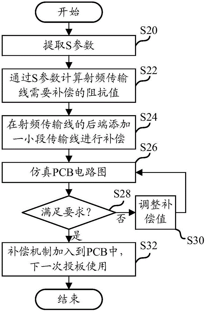
[0050] Step S12, calculating the impedance value of the radio frequency transmission line that needs to be compensated according to the scattering parameters. Wherein, the impedance value is a resistance value and a reactance value.

[0051] Step S14, based on the impedance value to be compensated, determine parameters of an open transmission line that needs to be added on the radio frequency transmission line, so as to perform mismatch compensation on ...


PUM


Abstract

The invention provides a mismatch compensation method and a mismatch compensation device for a radio-frequency transmission line. The mismatch compensation method for the radio-frequency transmission line comprises the following steps: extracting scattering parameters of the radio-frequency transmission line within the working frequency range of the radio-frequency transmission line; calculating an impedance value for which the radio-frequency transmission line needs to be compensated according to the scattering parameters; and based on the impedance value for which the radio-frequency transmission line needs to be compensated, determining parameters of an open-circuit transmission line that needs to be added to the radio-frequency transmission line, so that mismatch compensation of the radio-frequency transmission line can be carried out based on the added open-circuit transmission line. The mismatch compensation method and the mismatch compensation device adopting the technical scheme have the advantages that through the addition of the transmission line, the radio-frequency transmission line can be compensated for the mismatched impedance within the working frequency range of the radio-frequency transmission line, so that the mismatch problem of the radio-frequency transmission line can be effectively solved.

Description

technical field [0001] The present invention relates to the field of radio frequency technology, in particular to a mismatch compensation method for a radio frequency transmission line and a mismatch compensation device for a radio frequency transmission line. Background technique [0002] During the wiring process of a radio frequency PCB (Printed Circuit Board, printed circuit board), it is often encountered that due to space or other wiring constraints, a certain short transmission line cannot be in an ideal state, which will cause impedance mismatch of the transmission line. For example: due to the RF port output of the RF transceiver and the through-holes, wrong holes, and incomplete reference grounds in the transition from the microstrip line to the stripline, etc., there will be mismatch problems in the transmission line. [0003] When the problem of transmission line mismatch is solved by adding matching components (such as capacitors, inductors, resistors, etc.), du...

Claims


Application Information

Patent Timeline
IPC IPC(8): H05K3/00
CPCH05K3/0002H05K2201/0776H03H11/28
Inventor 信哲鑫
Owner YULONG COMPUTER TELECOMM SCI (SHENZHEN) CO LTD
Why Eureka
Try Eureka