A vacuum system capable of using heat generated by concentrated tail gas

A vacuum concentration and tail gas technology, which is applied in the direction of evaporator accessories, evaporation, chemical instruments and methods, etc., can solve the problems of energy waste and high tail gas temperature, and achieve the effects of increased concentration output, easy operation, and intuitive control methods

Inactive Publication Date: 2017-02-22
浙江惠光生化有限公司
View PDF7 Cites 1 Cited by
  • Summary
  • Abstract
  • Description
  • Claims
  • Application Information

AI Technical Summary

Problems solved by technology

[0002] At present, in industrial production, it is often encountered that multiple sets of vacuum concentration devices are required to carry out vacuum concentration at the same time. When steam heating is used, the exhaust gas temperature is relatively high, resulting in energy waste.

Method used


Image

  • A vacuum system capable of using heat generated by concentrated tail gas
  • A vacuum system capable of using heat generated by concentrated tail gas
  • A vacuum system capable of using heat generated by concentrated tail gas

Examples


Embodiment Construction

[0017] In order to enable those skilled in the art to better understand the technical solution of the present invention, its specific implementation will be described in detail below in conjunction with the accompanying drawings:

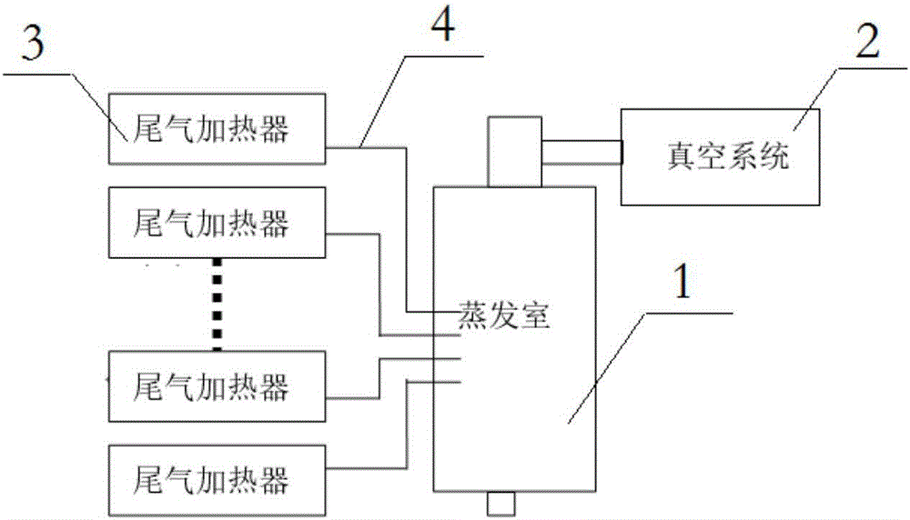
[0018] see figure 1 , figure 2 with image 3 , the best embodiment of the present invention, a vacuum concentrated tail gas thermal energy utilization system, including an evaporation chamber 1, a vacuum device 2, a number of exhaust heaters 3 and a number of feed pipes 4.

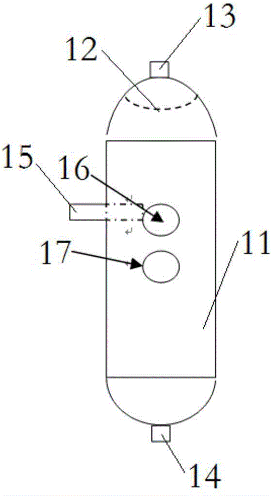
[0019] see Figure 4 , the evaporation chamber 1 includes a tank body 11 and a spherical anti-shock baffle 12, the top of the tank body 11 is provided with an air suction port 13, the spherical anti-shock baffle 12 is arranged in the tank body 11 and is located directly below the air suction port 13, the tank body The bottom end of 11 is provided with discharge port 14, and the wall surface of tank body 11 is provided with feed port 15, feed observation hole 16 and liquid le...


PUM


Abstract

The invention discloses a vacuum system capable of using heat generated by concentrated tail gas. The system comprises an evaporation chamber, a vacuum device, several tail gas heaters and several material inlet pipes. The evaporation chamber comprises a tank body and a spherical baffle plate. The top end of tank body is provided with an air extraction hole. The spherical baffle plate is located in the tank body and is placed squarely below the air extraction hole. The bottom of the tank body is provided with material outlets. The lateral side of the tank body is provided with material inlets, an inlet material observation hole and a fluid level observation hole. Viewing glass is placed at both the inlet material observation hole and the fluid level observation hole. The vacuum device is communicated with the air extraction hole of the evaporation chamber. The material outlets of several tail gas heaters pass through several material inlet pipes to communicate with the material inlets of the evaporation chamber. Each of the material inlet pipes is provided with a material inlet valve. The system can effectively utilize the heat generated by the tail gas. On the premises of increasing the concentrated output of tail gas, the system has the advantage of having no new additional energy consumption, being simple in operation and having a straightforward control manner.

Description

technical field [0001] The invention relates to a heat energy utilization system of vacuum concentrated tail gas. Background technique [0002] At present, in industrial production, it is often encountered that multiple sets of vacuum concentration devices are required to carry out vacuum concentration at the same time. When steam heating is used, the exhaust gas temperature is relatively high, resulting in energy waste. Contents of the invention [0003] The purpose of the present invention is to overcome the defects of the prior art and provide a heat energy utilization system for vacuum concentrated tail gas, which can effectively utilize the heat of the tail gas and increase the concentration output without consuming new heat energy. [0004] The technical solution to achieve the above purpose is: a vacuum concentrated tail gas thermal energy utilization system, including an evaporation chamber, a vacuum device, a number of tail gas heaters and a number of feed pipes, ...

Claims


Application Information

Patent Timeline
Patent Type & Authority Applications(China)
IPC IPC(8): B01D1/00B01D1/30
CPCB01D1/0058B01D1/007B01D1/30
Inventor 费朱建
Owner 浙江惠光生化有限公司
Why Eureka
Try Eureka