A high-efficiency induction blowing device and a pulse bag filter for a dust collector

A technology of blowing device and dust collector, which is applied in the direction of chemical instruments and methods, separation of dispersed particles, filtration of dispersed particles, etc., can solve the problems of low dust removal efficiency, poor dust removal effect, and influence on dust removal efficiency of dust collectors, etc., and achieves improvement Dust removal efficiency, improvement of dust removal effect, and effect of ensuring dust removal efficiency

Active Publication Date: 2018-08-28
四川实创微纳科技有限公司
View PDF1 Cites 0 Cited by
  • Summary
  • Abstract
  • Description
  • Claims
  • Application Information

AI Technical Summary

Problems solved by technology

[0005] The above-mentioned pulse bag filter is the same as the existing pulse bag filter. The inner cavity of the dust collector is divided into several small chambers, and a filter bag is placed in each small chamber, but none of them are equipped with separate chambers for off-line cleaning. The ash structure, when cleaning the dust, either stops the dust collector to complete the dust removal, which affects the dust removal efficiency of the dust collector; or fills the chamber with positive pressure when the dust collector is working, so that the positive pressure and negative pressure air affect each other , offset each other, the cleaning efficiency is low, and the cleaning effect is poor

Method used


Image

  • A high-efficiency induction blowing device and a pulse bag filter for a dust collector
  • A high-efficiency induction blowing device and a pulse bag filter for a dust collector
  • A high-efficiency induction blowing device and a pulse bag filter for a dust collector

Examples


Embodiment 1

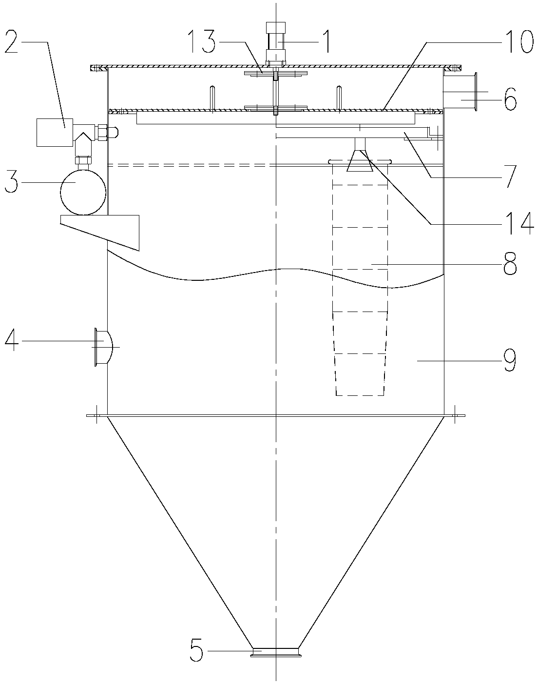
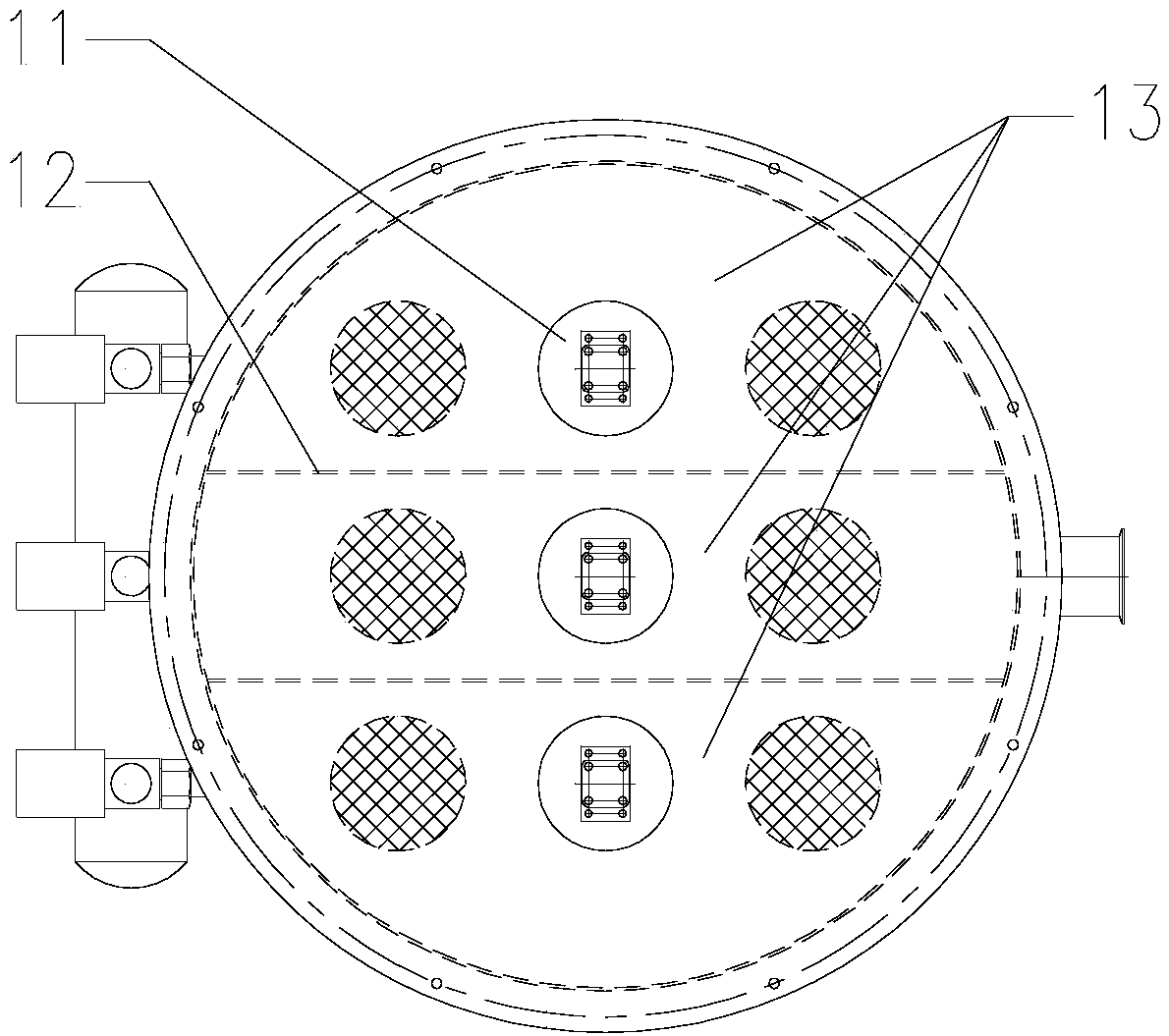
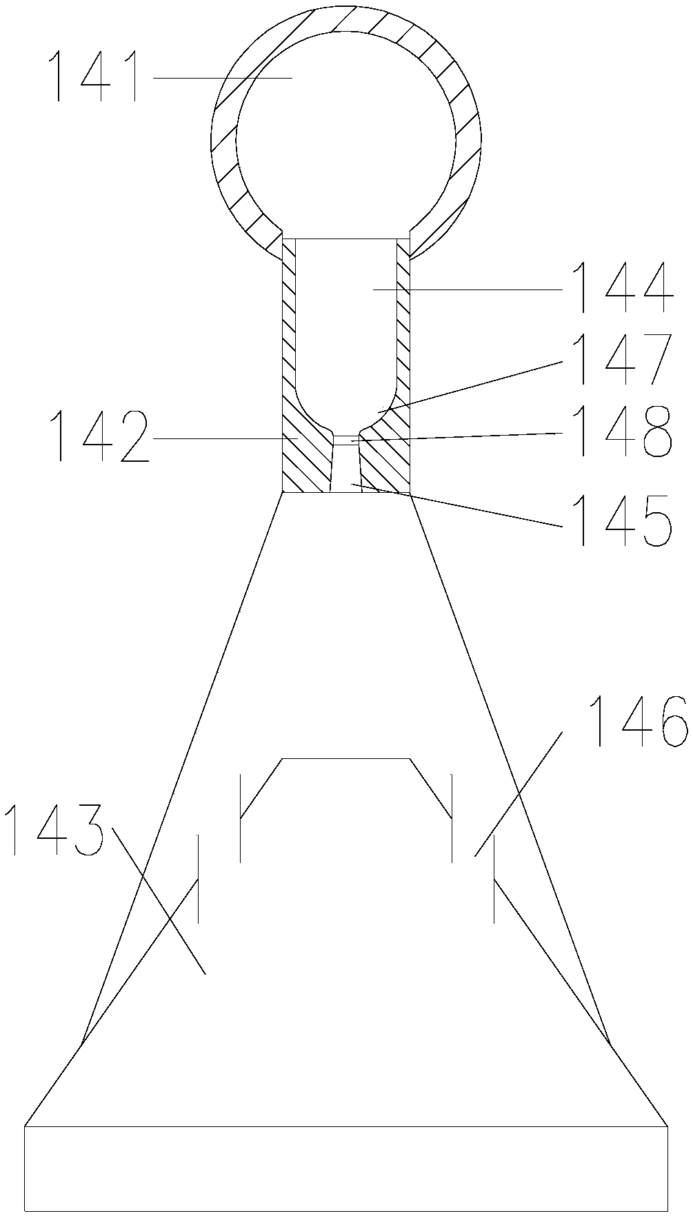
[0045] A high-efficiency induction blowing device for a dust collector, including a blowing branch pipe 141. One end of the blowing branch pipe 141 should communicate with the blowing pipe 7 in the corresponding clean air small chamber, and the other end of the blowing branch pipe 141 is connected with a supersonic The induction nozzle 142 , the other end of the supersonic induction nozzle 142 communicates with an airflow diffuser 143 , and the airflow diffuser 143 is provided with a diffuser air hole 146 . The high-speed and high-pressure airflow in the blowing pipe 7 can be sprayed out from the scattering air hole 146 of the airflow scattering device 143 after passing through the spraying branch pipe 141, the supersonic induction nozzle 142, and the airflow diffuser 143 successively, and is sprayed by the scattering airhole 146 of the airflow diffuser 143. The high-speed and high-pressure gas will directly act on the filter bag 8 to clean up the dust on the filter bag 8, so a...

Embodiment 2

[0047] On the basis of embodiment one, the ratio of the outer diameter of the supersonic induction nozzle 142 to the outer diameter of the injection branch pipe 141 is 1:2, and the ratio of the length of the supersonic induction nozzle 142 to the outer diameter of the injection branch pipe 141 The ratio of the length of the airflow diffuser 143 to the length of the supersonic induction nozzle 142 is 1.5:1, and the ratio of the opening diameter of the airflow diffuser 143 to the diameter of the supersonic induction nozzle 142 is 4:1.

Embodiment 3

[0049] On the basis of Embodiment 1 or Embodiment 2, the airflow channel of the supersonic induction nozzle 142 is the first steady-flow air hole 144 and the pressurized air hole 145. The booster air hole 145 is located on the air outlet side of the supersonic induction nozzle 142, the first steady-flow air hole 144 communicates with the booster air hole 145, and the inner diameter of the booster air hole 145 gradually increases along the airflow direction. In addition, a spherical transitional air hole 147 and a second steady-flow air hole 148 can also be arranged sequentially between the first steady-flow air hole 144 and the pressurized air hole 145, and the airflow in the supersonic induction nozzle 142 passes through the first steady-flow air hole 144, spherical After the transition air hole 147, the second steady flow air hole 148, and the pressurized air hole 145, enter the airflow diffuser 143; A smooth transition is achieved between the air holes 145 , which reduces t...


PUM


Abstract

The invention discloses an efficient induced jetting device of a deduster and a pulse bag-type deduster, belongs to the technical field of bag-type dedusters of dedusting equipment, and aims to increase dust cleaning efficiency. The efficient induced jetting device of the deduster comprises a branch jetting tube, one end of the branch jetting tube is communicated with a jetting tube in a corresponding small purifying chamber, the other end of the branch jetting tube is communicated with a supersonic induced jetting nozzle, the other end of the supersonic induced jetting nozzle is communicated with an airflow diffuser, and diffusing air holes are formed in the airflow diffuser. An inner cavity of the deduster is separated into a plurality of small purifying chambers, and the efficient induced jetting device is arranged above a filter bag in every small purifying chamber. The efficient induced jetting device is applicable to a bag-type deduster.

Description

technical field [0001] The invention belongs to the technical field of dust removal equipment, and relates to a bag filter, in particular to a bag filter with the function of off-line dust cleaning in separate chambers. Background technique [0002] The bag filter is an essential and important equipment in the powder production line. Its performance determines the output and gas emission indicators of the production system. The bag filter is a dry dust filter device. It is suitable for capturing fine, dry, non-fibrous dust. The dust-containing gas is filtered by the filter function of the fiber fabric. When the dust-containing gas enters the bag filter, the dust with large particles and specific gravity settles down due to the action of gravity and falls into the ash hopper, while the gas containing finer dust When passing through the filter material, the dust is blocked and the gas is purified. [0003] The pulse bag filter is a new type of high-efficiency pulse bag filt...

Claims


Application Information

Patent Timeline
Patent Type & Authority Patents(China)
IPC IPC(8): B01D46/02B01D46/04
CPCB01D46/023B01D46/04
Inventor 汪林袁祖江胡怀勇
Owner 四川实创微纳科技有限公司
Why Eureka
Try Eureka