A vortex radial acceleration dust removal and mist removal device

A demisting device, vortex technology, applied in the direction of combination device, dispersed particle separation, chemical instruments and methods, etc., can solve the problem that it is not enough to achieve efficient separation of dust particles and mist droplets from air flow, and cannot avoid the accumulation of dust particles and mist droplets And it is entrained by the air flow, affecting the effect of flue gas purification, etc., to achieve the effect of compact structure, preventing secondary entrainment, and convenient installation

Active Publication Date: 2018-08-24
广州创能电力技术工程有限公司
View PDF1 Cites 0 Cited by
  • Summary
  • Abstract
  • Description
  • Claims
  • Application Information

AI Technical Summary

Problems solved by technology

However, the patented dust and mist removal device only relies on the centrifugal force generated by the tangential movement of dust particles and mist droplets generated by the cyclone, which is not enough to achieve efficient separation of dust particles and mist droplets from the air flow; nor can it avoid dust particles and mist droplets Under the attraction of the low pressure in the center of the vortex, it gathers towards the center of the airflow and is entrained by the airflow; the fine dust particles and mist droplets rising with the surrounding airflow are finally mixed into the main airflow, which affects the purification effect of the flue gas, and can be further improved Improve

Method used


Image

  • A vortex radial acceleration dust removal and mist removal device
  • A vortex radial acceleration dust removal and mist removal device
  • A vortex radial acceleration dust removal and mist removal device

Examples


Embodiment 1

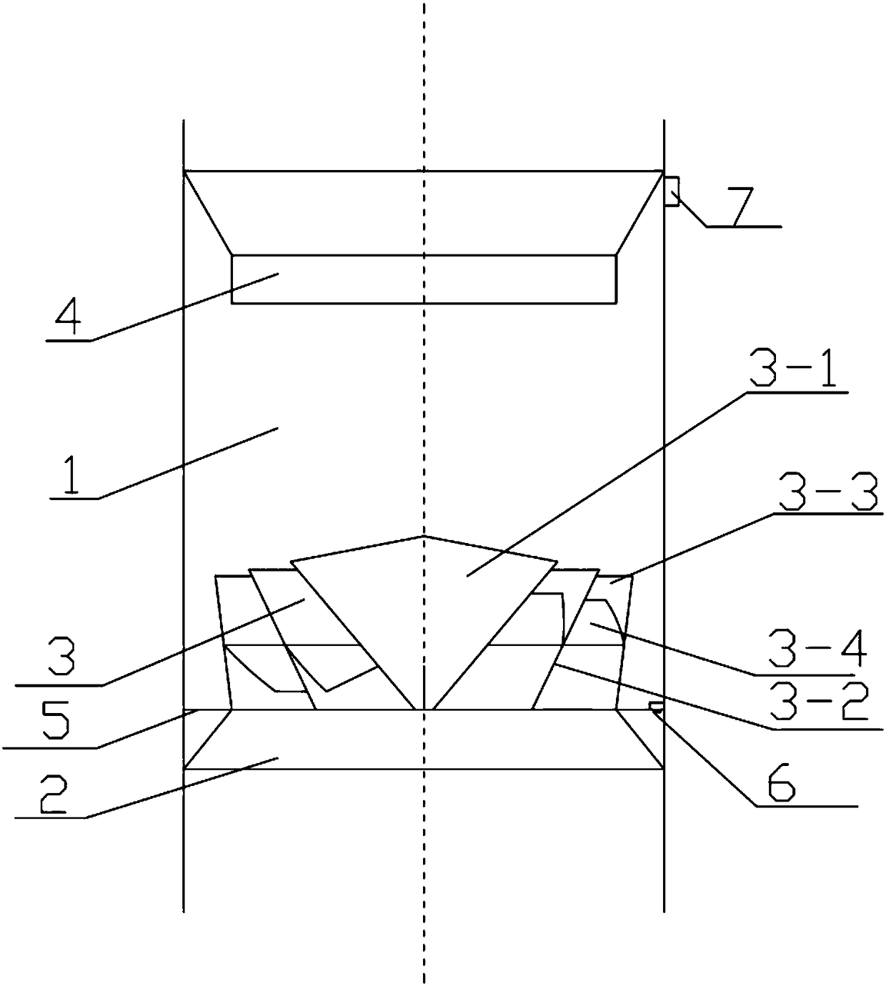
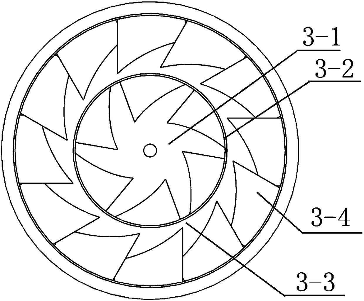
[0029] Such as Figure 1-Figure 4 As shown, in this embodiment, a vortex radial acceleration dedusting and mist removal device includes a cylinder body 1, an air inlet 2, a vortex accelerator 3, and an air outlet 4. The air inlet is arranged at the lower end of the cylinder body. The vortex accelerating body is installed on the air inlet through the support plate 5, and the air outlet is arranged at the upper end of the cylinder body; the vortex accelerating body 3 includes a central body 3-1, an expanding tube 3-2, and an annular air duct 3-3 and vortex blades 3-4, the central body 3-1 and the expander 3-2 are coaxially arranged, and both are arranged on the support plate 5 and fixedly connected with the support plate; the central body 3- 1 is a sealed cavity, the shape of which is a curved body with a large top and a small bottom. The diameter of the gradually expanding tube 3-2 continuously expands from bottom to top, showing a hollow curved body with a large top and a smal...

Embodiment 2

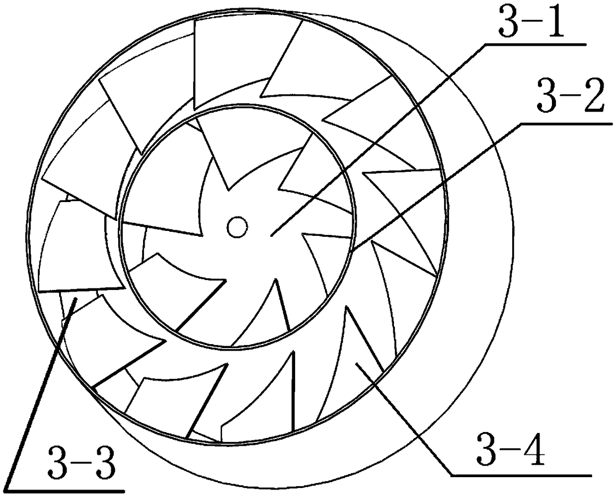
[0043] The technical solution of this embodiment is the same as that of Embodiment 1 except for the following technical features. The outer large order is arranged in sequence, and the multiple expanders are set as the first expander, the second expander...the Nth expander from the inside to the outside, and the central body and the first expander form a first ring Air duct, the first expander and the second expander form a second annular air duct...the N-1th expander and the Nth expander form the Nth annular air duct; each annular air duct is There are n swirl blades 3-4, and the swirl blades are fixedly connected with the central body or the diffuser for the air duct. In this embodiment, through the arrangement of multiple expanders, multiple annular air ducts can be formed, and n swirl blades are evenly arranged in each annular air duct, n≥3, and the swirl blades are respectively connected to the central body or the progressive The expansion pipes are fixedly connected, and ...


PUM


Abstract

The invention discloses a vortex radial acceleration dedusting and mist removal device, which comprises a cylinder body, an air inlet, a vortex acceleration body, and an air outlet. The support plate is installed on the air inlet, and the air outlet is arranged at the upper end of the cylinder; the vortex acceleration body includes a central body, an expander tube, an annular air channel and a vortex blade, and the center body and the expander tube are the same The shafts are arranged on the support plate and fixedly connected with the support plate; the central body is a sealed cavity, and the shape is a curved body with a large upper part and a smaller lower part. The diameter of the expanding tube expands continuously from bottom to top It is a hollow surface with a large top and a small bottom; the dust and mist removal device of the present invention has the advantages of compact structure, convenient maintenance, good separation effect, small smoke resistance, low operating cost, and has good application prospects.

Description

technical field [0001] The invention relates to the research field of flue gas dust removal, mist removal and purification treatment, in particular to a vortex radial acceleration dust removal and mist removal device. Background technique [0002] With the continuous improvement of environmental protection emission standards, the emission concentration limit of coal-fired boilers in thermal power plants in key areas in the "Emission Standards of Air Pollutants for Thermal Power Plants" has been set at 20mg / Nm 3 , especially in order to speed up the control of smog, various regions have successively put forward higher requirements for ultra-clean emissions from coal-fired boilers in thermal power plants, and the limit of smoke and dust emission concentration has reached 5mg / Nm 3 . [0003] After the bag filter, the dust emission value can be reduced to 30mg / Nm 3 In the following, although the limestone gypsum wet desulfurization process arranged after the dust collector has...

Claims


Application Information

Patent Timeline
Patent Type & Authority Patents(China)
IPC IPC(8): B01D50/00
CPCB01D45/14B01D45/16B01D50/40
Inventor 刘嵘岳昕
Owner 广州创能电力技术工程有限公司
Why Eureka
Try Eureka