Filter cleaner base shell mould

A filter and shell technology is applied in the field of die-casting molds for filter base shells, which can solve the problems of low production efficiency and high cost, and achieve the effects of high production efficiency, low cost, and reduced holding force.

Active Publication Date: 2017-02-22
NINGBO BODA MACHINERY
View PDF8 Cites 4 Cited by
  • Summary
  • Abstract
  • Description
  • Claims
  • Application Information

AI Technical Summary

Problems solved by technology

[0003] The invention solves the problems of high cost, low production efficiency and poor casting quality in the conventional core-pulling structure of the general die-casting mold, and provides a filter base shell mold, through the main body of the die-casting mold, two oil cylinders, The combined innovation of left and right sliders, left and right side slanting blocks and local cooling devices realizes that the filter base shell mold has simple and stable structure, low cost, high production efficiency, stable casting shape and dimension, good casting quality and excellent mold quality. Good cooling effect and fast cooling speed

Method used


Image

  • Filter cleaner base shell mould
  • Filter cleaner base shell mould
  • Filter cleaner base shell mould

Examples


Embodiment 1

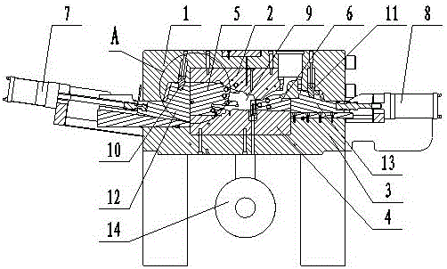
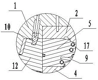
[0024] Embodiment one: combined with attached figure 1 and 2 , a filter base shell mold, comprising an upper mold frame 1, an upper mold core 2 arranged in the upper mold frame 1, a lower mold frame 3 and a lower mold core 4 arranged in the lower mold frame 3, the upper mold frame 1 is connected with the lower mold frame 3, on the left and right sides of the mould, between the upper mold core 2 and the lower mold core 4, there are respectively a left slider 5 and a right slider 6, and the ends of the left slider 5 and the right slider 6 The part is respectively provided with a left oil cylinder 7 and a right oil cylinder 8, and the combination of the upper mold core 2, the lower mold core 4, the left slider 5 and the right slider 6 forms the die-casting cavity 9 of the filter base shell, and the upper mold frame 1 is set There is a left side slanting block 10 suitable for the left slider 5 and a right side slanting block 11 suitable for the right slider 6. Near the die-castin...

Embodiment 2

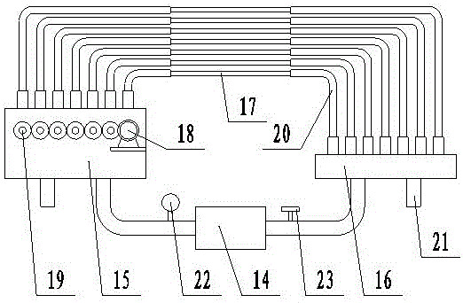
[0025] Embodiment two, combined with figure 1 , 2, 3, 4, 6, a filter base shell mold, including an upper mold frame 1, an upper mold core 2 arranged in the upper mold frame 1, a lower mold frame 3 and a lower mold arranged in the lower mold frame 3 Core 4, the upper mold frame 1 is connected with the lower mold frame 3, on the left and right sides of the mould, between the upper mold core 2 and the lower mold core 4, a left slider 5 and a right slider 6 are respectively provided, and the left slider 5 and the The end of the right slider 6 is respectively provided with a left oil cylinder 7 and a right oil cylinder 8, and the upper mold core 2, the lower mold core 4, the left slider 5 and the right slider 6 are combined to form the die-casting cavity 9 of the filter base shell , the upper mold frame 1 is provided with a left side slanting block 10 suitable for the left slider 5 and a right side slanting block 11 suitable for the right slider 6, near the die-casting cavity 9, t...

Embodiment 3

[0026] Embodiment three, combined with the attached figure 1 , 2 , 3, 5 and 6, a filter base housing mold, including an upper mold frame 1, an upper mold core 2 arranged in the upper mold frame 1, a lower mold frame 3 and a lower mold arranged in the lower mold frame 3 Core 4, the upper mold frame 1 is connected with the lower mold frame 3, on the left and right sides of the mould, between the upper mold core 2 and the lower mold core 4, a left slider 5 and a right slider 6 are respectively provided, and the left slider 5 and the The end of the right slider 6 is respectively provided with a left oil cylinder 7 and a right oil cylinder 8, and the upper mold core 2, the lower mold core 4, the left slider 5 and the right slider 6 are combined to form the die-casting cavity 9 of the filter base shell , the upper mold frame 1 is provided with a left side slanting block 10 suitable for the left slider 5 and a right side slanting block 11 suitable for the right slider 6, near the di...


PUM


Abstract

The invention discloses a filter cleaner base shell mould. The filter cleaner base shell mould comprises an upper mould frame, an upper mould core, a lower mould frame and a lower mould core, wherein the upper mould core is arranged in the upper mould frame, and the lower mould core is arranged in the lower mould frame. The upper mould frame and the lower mould frame are connected and arranged on the left side and the right side of the mould correspondingly. A left sliding block and a right sliding block are arranged between the upper mould core and the lower mould core. A left oil cylinder and a right oil cylinder are arranged at the end of the left sliding block and the end of the right sliding block correspondingly. The upper mould core, the lower mould core, the left sliding block and the right sliding block are combined to form a die casting cavity of a filter cleaner base shell. A left side oblique swinging block and a right side oblique swinging block are arranged on the upper mould frame, wherein the left side oblique swinging block is matched with the left sliding block, and the right side oblique swinging block is matched with the right sliding block. Partial cooling devices are arranged on the positions, nearby the die casting cavity, of the left sliding block and the right sliding block correspondingly. The filter cleaner base shell mould has the obvious beneficial effects that structure is simple and stable, cost is low, production efficiency is high, the size of a casting outline is stable, casting quality is good, and the mould is good in heat dissipation effect and high in heat dissipation speed.

Description

technical field [0001] The invention relates to the technical field of die-casting molds, in particular to a die-casting mold for filter base shells. Background technique [0002] Die-casting mold refers to a mold in which liquid metal is poured into the cavity of the mold, and a series of processes such as pressurized forging are used to shape the casting. Due to the complex structure, many castings are difficult to demould after forming. In order to release the castings smoothly, the structure of adding mosaic blocks or sliders is usually used in the die-casting mold, and it is realized by core pulling through the hydraulic cylinder. In the market, many slider core-pulling structures have the problems of high cost, low production efficiency and poor casting quality. However, the structure of the general die-casting mold in the prior art does not effectively solve the above-mentioned problems. For example, the Chinese Patent Authorization Announcement No. CN 203680683 U,...

Claims


Application Information

Patent Timeline
Patent Type & Authority Applications(China)
IPC IPC(8): B22D17/22
CPCB22D17/22B22D17/2218
Inventor 陆逵
Owner NINGBO BODA MACHINERY
Why Eureka
Try Eureka