
Press-mounting device for rectification window of aviation turbine cooler and press-mounting method

An aviation turbine and press-fitting device technology, which is applied in metal processing, metal processing equipment, manufacturing tools, etc., can solve the problems of easy tearing of the sealing ring installation groove, easy cutting of the sealing ring, uneven force, etc. Achieving good scientificity, ensuring installation quality and uniform force

Active Publication Date: 2017-02-22
GUIZHOU YONGHONG AVIATION MACHINERY
View PDF4 Cites 4 Cited by
  • Summary
  • Abstract
  • Description
  • Claims
  • Application Information

AI Technical Summary

Problems solved by technology

[0008] The purpose of the present invention is to provide a press-fitting device and a press-fitting method for the rectifying window of the aviation turbine cooler, so as to solve the problem that the sealing ring is easily cut and the sealing ring installation groove exists during the installation process of the rectifying window of the existing aviation turbine cooler. Easy to be torn, uneven force, prone to deflection, low installation accuracy and other problems

Method used


Image

  • Press-mounting device for rectification window of aviation turbine cooler and press-mounting method
  • Press-mounting device for rectification window of aviation turbine cooler and press-mounting method
  • Press-mounting device for rectification window of aviation turbine cooler and press-mounting method

Examples


Embodiment 1

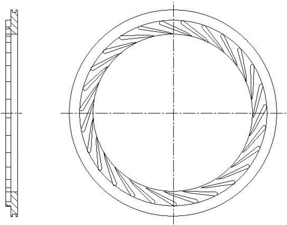
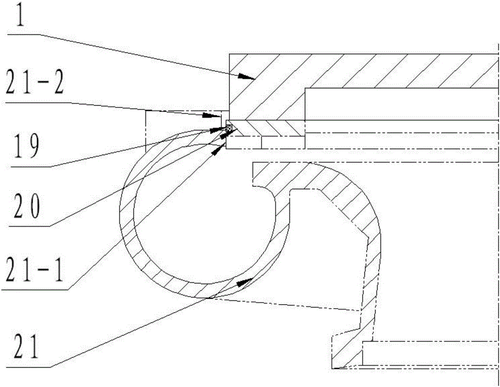
[0054] Example 1: requires an assembly such as Figure 1-2 The rectification window shown is A20 when the

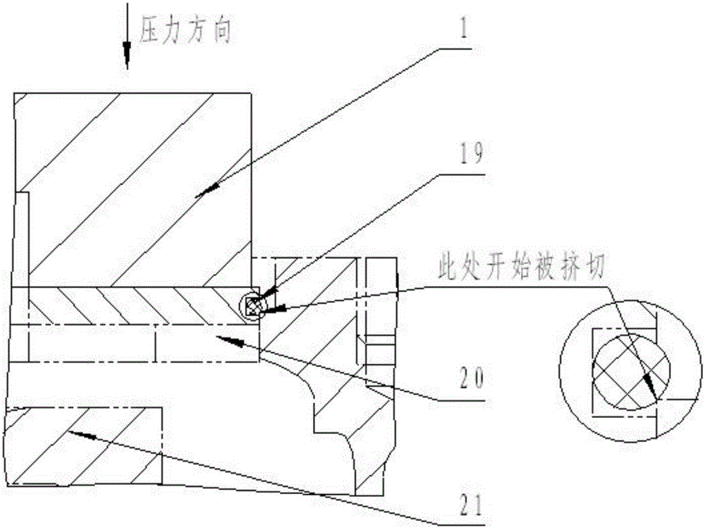
[0055] Select the corresponding guide mechanism 6 according to the figure numbers of the rectifying window A20 and the turbine cover A21, and check whether the surface of the guide mechanism 6 and the sealing ring A19 will be in contact with or not; Enter the screw B18 to make it consistent with the height of the guide 8 and block the guide 8; loosen the nut A10 on the pressure rod 7, and adjust the radial position of the pressure rod 7 according to the size of the rectification window A20, so that the guide mechanism 6 can be set on all On the pressure rod 7, make the pressure rod 7 fit the inner hole A6-4 of the guide mechanism 6, tighten the nut A10 on the pressure rod 7; withdraw the screw B18 to separate it from the guide 8; put the rectifying window A20 Place the assembly parts with the seal ring A19 in the guide mechanism 6, and place the guide mechanism 6 on the...

Embodiment 2

[0056] Example 2: requires an assembly such as Figure 11-12 The rectification window shown is B23 when the

[0057] (1) The nozzle on the rectifying window B23 is fully open along the circumference ( Figure 11 ), so it is installed with the turbine cover B24 ( Figure 12 ) when there is no angular positioning requirement;

[0058] (2) The turbine cover B24 has a 24-1 inner hole for installing the rectifying window B23, and another group of 24-2 threaded holes related to the axial position of the 24-1 inner hole, providing a guide mechanism B ( Figure 13 ) positioning benchmark.

[0059] (3) Guide mechanism B ( Figure 13 ) consists of a positioning piece B25, a guide B26, and a screw 27. The angle of the guide B26 taking the conical surface 26-2 bell mouth is 30°, and the radius of the 26-1R profile is 4 of the cross-sectional diameter of the seal ring 22 φ2.5 The times are R10, the 26-3 inner hole is consistent with the size and precision of the 24-1 inner hole where ...

Embodiment 3

[0063] needs to be assembled as Figure 15-16 When the rectification window C30 is shown:

[0064] (1) The nozzle on the rectification window C29 is divided along the circumference ( Figure 15 ), so there is an angular positioning requirement when it is installed with the turbine cover C30;

[0065] (2) The turbine cover C30 has a 30-1 inner hole for installing the rectifying window C29, and another group of 30-2 threaded holes related to the axial position of the 30-1 inner hole, providing a guide mechanism C ( Figure 17 ) positioning benchmark.

[0066] (3) The guide mechanism C is composed of a positioning piece C31, a guide C32, a screw 33, a positioning block 34, a positioning screw 35, a nut 36, a positioning screw pile 37, a nut 38, and a positioning pin 39. The guide C32 takes a conical surface 32- 2 The angle of the bell mouth is 30°, 32-1, the radius of the R-shaped surface is 5 times of the cross-sectional diameter φ2 of the sealing ring 28 is R10, and the inne...


PUM


Abstract

The invention discloses a press-mounting device for a rectification window of an aviation turbine cooler and a press-mounting method. The press-mounting device for the rectification window of the aviation turbine cooler comprises a base plate. Stand columns are inserted in the two sides of the top end of the base plate correspondingly. A cross beam is mounted at the top ends of the stand columns. A threaded hole is formed in the middle of the cross beam. A screw is inserted into the threaded hole. A ball is arranged at the bottom end of the screw. A guide piece is hinged to the ball and comprises a disc located in the middle, and a plurality of supporting arms are evenly arranged outside the disc. A rectangular groove is formed in the middle of each supporting arm. Pressing rods are inserted into the rectangular grooves. A disc chuck is mounted on the upper portion of the guide piece in a clamped mode and comprises a round disc body. A through hole is formed in the center of the disc body, arc-shaped grooves are formed in the disc body, and handles are fixedly connected to the edge of the disc body. The top ends of the pressing rods stretch out of the guide piece and are fixed through nuts at the top after penetrating through the arc-shaped grooves. By adoption of the press-mounting device for the rectification window of the aviation turbine cooler and the press-mounting method, the problems that in the prior art, when the rectification window of the aviation turbine cooler is mounted, a sealing ring is prone to cut damage, a sealing ring mounting groove is prone to being torn, stress is nonuniform, deflection occurs easily, and the mounting precision is poor can be solved.

Description

technical field [0001] The invention relates to the technical field of installation of a rectification window of an aero-engine turbine cooler, in particular to a press-fitting device and a press-fitting method for a rectification window of an aero-engine turbine cooler. Background technique [0002] The rectification window is a key component in the aviation turbine cooler. Its main function is to make the air with higher temperature and pressure drawn from the engine compressor expand and accelerate in the nozzle of the rectification window, and convert the heat energy in the air into air. The kinetic energy flows out from the rectification window and drives the turbine disk to do work, reducing the temperature and pressure of the air. Such as figure 1 The rectifying window shown has a Laval tube-like nozzle composed of blades, which plays a key role, is difficult to process, and has high manufacturing costs. In the previous turbine cooler assembly, the rectification win...

Claims


Application Information

Patent Timeline
IPC IPC(8): B23P19/02
CPCB23P19/02
Inventor 宋玉祥
Owner GUIZHOU YONGHONG AVIATION MACHINERY
Learn More