
High-speed direct-driven machine tool fourth shaft

A direct drive, machine tool technology, used in metal processing machinery parts, large fixed members, metal processing equipment, etc., can solve problems such as difficult waterproof sealing

Inactive Publication Date: 2017-02-22
GUANGDONG POLYTECHNIC NORMAL UNIV
View PDF5 Cites 1 Cited by
  • Summary
  • Abstract
  • Description
  • Claims
  • Application Information

AI Technical Summary

Problems solved by technology

Moreover, high-speed rotation also involves the problem of waterproof sealing

Method used


Image

  • High-speed direct-driven machine tool fourth shaft

Examples


Embodiment Construction

[0026] The preferred embodiments of the present invention will be described in detail below in conjunction with the accompanying drawings, so that the advantages and features of the present invention can be more easily understood by those skilled in the art, so as to define the protection scope of the present invention more clearly.

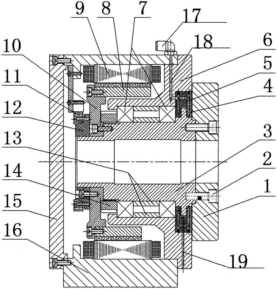
[0027] refer to figure 1 , an example of the present invention, a fourth axis of a high-speed direct drive machine tool, mainly includes:

[0028] The body 16 is equipped with a motor stator 9, a motor rotor 8, a bearing seat 6, a bearing 7 installed on the bearing seat 6, and a rotary shaft 3 from the outside to the inside, and the rotary shaft 3 is installed in the In the bearing 7, the lower end of the rotary shaft 3 is locked to the inner ring of the bearing 7 through the lock nut 14, and the motor rotor 8 is connected to the rotary shaft 3 through the rotor connecting seat 10;

[0029] Rear air floatation plate 5, described rear air floatat...


PUM


Abstract

The invention relates to a high-speed direct-driven machine tool fourth shaft. The high-speed direct-driven machine tool fourth shaft is characterized by comprising a machine body, a back air flotation plate, a front air flotation plate, a rotating disc, an encoder, an intake joint and a guide hole, wherein a motor stator, a motor rotor, a bearing base, a bearing mounted on the bearing base and a rotating shaft are mounted in the machine body in sequence from outside to inside; the rotating shaft is mounted in the bearing; the motor rotor is connected with the rotating shaft; the back air flotation plate is mounted on the bearing base; the front air flotation plate is mounted on the back air flotation plate; the front air flotation plate and the back air flotation plate are respectively not contacted with the disc surface of the rotating shaft; a radial gap is formed between the front air flotation plate and the rotating shaft; the rotating disc is mounted on the rotating shaft through a screw; the encoder is mounted in the machine body; gaps formed by the front air flotation plate and the back air flotation plate with the rotating shaft are communicated to the intake joint through intake holes; and the guide hole is formed in the bearing base, and is communicated with the intake holes. The high-speed direct-driven machine tool fourth shaft solves the waterproof difficulty of high-speed rotation to cutting liquid, can reduce the power loss, and improves the machining efficiency.

Description

technical field [0001] The invention belongs to the field of the fourth axis for machining of numerical control machine tools, in particular to a fourth axis of a high-speed direct drive machine tool. Background technique [0002] Generally, when the workpiece is not positioned in space, it has six degrees of freedom, X\Y\Z three linear displacement degrees of freedom and the corresponding A\B\C three rotational displacement degrees of freedom. The six degrees of freedom usually use the X\Y\Z of the Cartesian coordinate system to express the three linear axes, and use the corresponding A\B\C to express the three rotary axes. For example, when designing a multi-axis CNC machine tool, that is, a machining center, the number of axes needs to be set according to the planning of the machining object. The more common in the market is the three-axis CNC machining center, which has three linear displacement axes of X\Y\Z. The so-called four-axis machining center generally adds a r...

Claims


Application Information

Patent Timeline
IPC IPC(8): B23Q1/25
CPCB23Q1/25
Inventor 孙洪颖李纬华
Owner GUANGDONG POLYTECHNIC NORMAL UNIV
Learn More