Fixture for rudder blades

A technology for tooling fixtures and rudder pieces, which is applied to manufacturing tools, clamps, etc., can solve the problem of inability to clamp rudder pieces, and achieve the effects of improving processing production efficiency, low manufacturing cost, and convenient disassembly and assembly.

Active Publication Date: 2017-02-22
成都久欣时代科技有限公司
View PDF5 Cites 1 Cited by
  • Summary
  • Abstract
  • Description
  • Claims
  • Application Information

AI Technical Summary

Problems solved by technology

The patent "a rudder blade rotation withdrawal device (patent number: CN201110332981.6)" discloses a rudder blade rotation withdrawal device, although the patent can complete the rudder blade withdrawal, but it cannot clamp the rudder blade

Method used


Image

  • Fixture for rudder blades
  • Fixture for rudder blades
  • Fixture for rudder blades

Examples


Embodiment Construction

[0019] The present invention will be further described below in conjunction with the accompanying drawings, but the protection scope of the present invention is not limited to the following description.

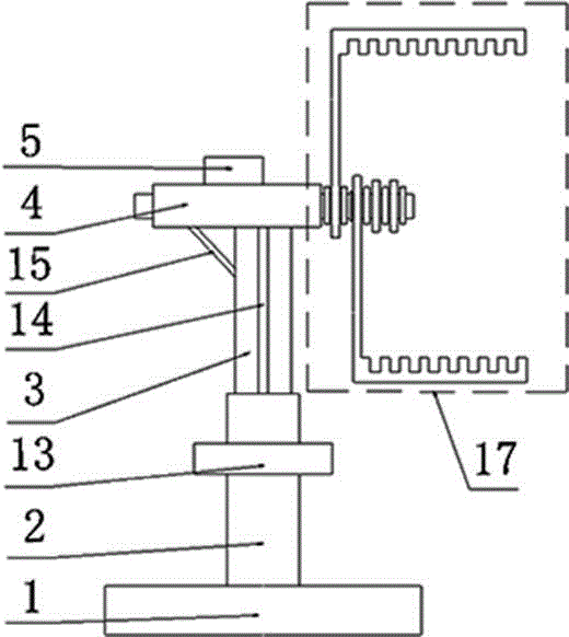
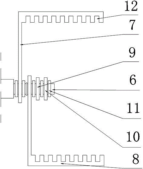
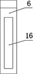
[0020] Such as Figure 1-Figure 4 Shown, a kind of rudder gear fixture, it comprises base 1, sleeve 2, expansion rod 3, upper base 4, cylinder 5 and clamping device 17, one end of sleeve 2 is installed on the base 1, the other end of sleeve 2 Connect with one end of telescopic rod 3, the other end of telescopic rod 3 is fixedly installed with the lower surface of upper base 4, and the upper surface of upper base 4 is equipped with cylinder 5; Described clamping device 17 comprises output shaft 6, steel clip A7, steel Clamp B8, steel clamp C9, steel clamp D10 and fastening nut 11, steel clamp A7, steel clamp B8, steel clamp C9 and steel clamp D10 are installed on the output shaft 6 in sequence, and the space between two adjacent steel clamps is installed Tighten the nut 11. ...


PUM


Abstract

The present invention relates to the technical field of fixtures for rudder blades, and specifically discloses a fixture for rudder blades. The fixture for rudder blades comprises a base, a sleeve, a telescopic rod, an upper seat, an air cylinder, and a clamping device. One end of the sleeve is mounted on the base, while the other end of the sleeve is connected to one end of the telescopic rod; the other end of the telescopic rod is fixedly mounted with the lower surface of the upper seat, and the air cylinder is mounted on the upper surface of the upper seat. The clamping device comprises an output shaft, steel clip A, steel clip B, steel clip C, steel clip D, and fastening nuts. The steel clip A, the steel clip B, the steel clip C and the steel clip D are mounted on the output shaft in sequence, and a fastening nut is mounted between two adjacent steel clips for the sake of separation. According to the present invention, a new fixture for rudder blades is designed on the basis of some prior art, which maintains the advantages of the prior art and also has the features of convenience in clamping, high clamping efficiency, good universality, and the like.

Description

technical field [0001] The invention relates to the technical field of tooling fixtures for rudder blades, in particular to a tooling fixture for rudder blades. Background technique [0002] The guided projectile needs to be launched with a barrel weapon. Before launching, it is first installed in the barrel, and the inner diameter of the barrel matches the shape of the guided projectile for positioning. The rudder blades of the guided projectile are distributed along the circumference of the shell axis. In order to meet the above requirements, the rudder blades must be folded and closed before launching. The rotation of the film realizes the guidance function of the shell. It can be seen that the rudder plate is an important device for shell guidance, and occupies a very important position in the shell guidance system. The patent "a rudder blade rotation and withdrawal device (patent number: CN201110332981.6)" discloses a rudder blade rotation and withdrawal device. Altho...

Claims


Application Information

Patent Timeline
IPC IPC(8): B25B5/14B25B5/16
CPCB25B5/006B25B5/145B25B5/16B25B5/163
Inventor 郭健辉
Owner 成都久欣时代科技有限公司
Why Eureka
Try Eureka