A rubber vacuum-assisted screw extrusion continuous dehydration drying method and equipment for preventing material leakage

A vacuum-assisted, screw-extruded technology, which is applied in the field of post-treatment of synthetic rubber or wet-mixed rubber, can solve the problems of cumbersome operation, easy discharge of extruder exhaust, and impracticality, achieving a high degree of automation, Great practical value, the effect of continuous process

Active Publication Date: 2021-04-30
QINGDAO UNIV OF SCI & TECH
View PDF16 Cites 0 Cited by
  • Summary
  • Abstract
  • Description
  • Claims
  • Application Information

AI Technical Summary

Problems solved by technology

The reference document and this technical solution belong to the same technical field, among which 201420373553.7 is the closest prior art, but the use of the screw thread can also generate downward extrusion force on the upwelling plastic material, and the upwelling or The overflow plays a certain role in restraining, but there is no disclosure of the anti-spill shaftless screw device with motor control and an angle with the axis of the present invention. The technical solution disclosed in the above reference document needs to be connected with a more complicated circuit control device, and the operation is cumbersome. , and the exhaust port of the extruder is easy to emit material, there is no public use of equal-depth variable-pitch screw to increase the compression ratio in the compression section, so that the temperature and pressure are also gradually increased so that the moisture in the rubber is extruded, and When the rubber is used to reach the exhaust section, due to the deep groove of the screw and the large pitch, a lower pressure is formed, so that the water molecules, air and low molecular volatiles in the rubber escape, and are drawn out by a vacuum pump through the exhaust hole, thereby realizing The technical scheme of dehydration and drying of rubber has no anti-flush exhaust device, so it is not practical in actual production

Method used


Image

  • A rubber vacuum-assisted screw extrusion continuous dehydration drying method and equipment for preventing material leakage
  • A rubber vacuum-assisted screw extrusion continuous dehydration drying method and equipment for preventing material leakage
  • A rubber vacuum-assisted screw extrusion continuous dehydration drying method and equipment for preventing material leakage

Examples


Embodiment Construction

[0027] The following will clearly and completely describe the technical solutions in the embodiments of the present invention with reference to the drawings in the embodiments of the present invention.

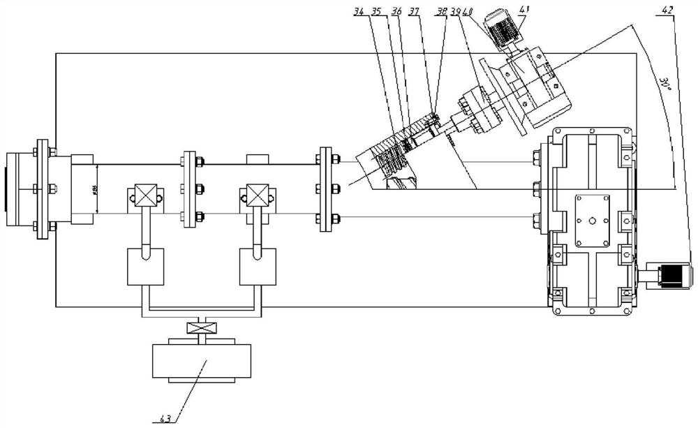
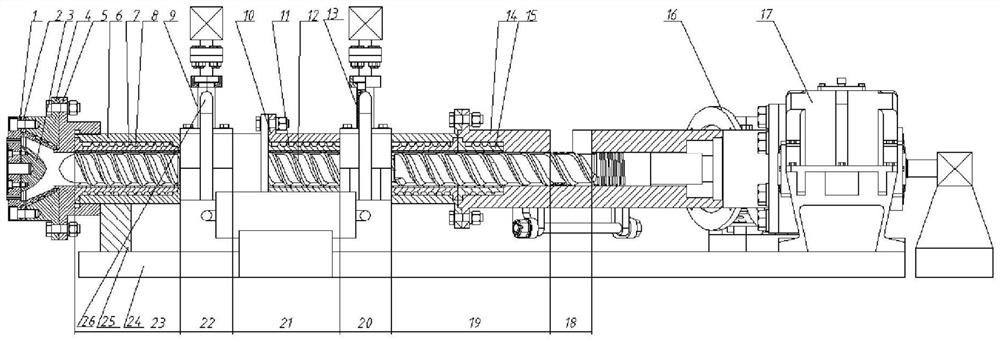
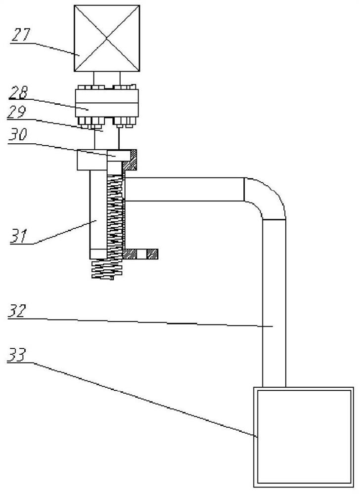
[0028] like figure 1 , figure 2 , image 3 As shown in the figure, a rubber vacuum-assisted screw extrusion continuous dehydration and drying anti-emission equipment, its main structure includes a nose die 1, a nose jacket 2, a shunt shuttle 3, a nesting body 4, a connecting body 5, and a machine barrel Section 6, Cooling water jacket Section 7, Bushing 8, Vacuum pumping device 1 9, Barrel 2 section 10, Cooling water jacket 2 section 11, Screw 12, Vacuum pumping device 2 13, Machine barrel 3 section 14, Cooling water jacket Three sections 15, feeding device 16, reduction box 17, base 24, bracket 25, the machine head is composed of four parts: nose die 1, machine head jacket 2, shunt shuttle 3, nesting body 4, machine barrel is composed of The first section of the barrel is...


PUM


Abstract

The invention discloses a method and equipment for continuous dehydration and drying of rubber vacuum auxiliary screw extruding to prevent rubber from dehydrating The purpose of glue leakage when exhausting. Compared with the screw thread, the shaftless screw device controlled by the motor can generate a greater downward thrust on the rubber material, so that the rubber material can slowly fill the shaftless space and screw with the rubber material, which enhances the Anti-spill effect; while the moisture in the rubber material is overflowed through mechanical extrusion and two negative pressures, the two water negative pressure overflows make the rubber material dry more fully, and there is no need to connect a more complicated circuit control device, and the operation is simple.

Description

technical field [0001] The invention belongs to the post-treatment field of synthetic rubber or wet mixing rubber, and relates to a vacuum-assisted screw extrusion dehydration drying method and equipment. Background technique [0002] The drying of rubber is an important process in the rubber production process, which occupies a considerable proportion in the total production energy consumption, equipment investment, and operating costs. At the same time, the drying process also directly affects the color, volatile content, and polymer content of rubber products. Parameters such as degradation and degree of crosslinking. [0003] In the early 1940s, the United States developed the production flow field of the emulsion method of styrene-butadiene rubber. In the post-processing, the drying process of vacuum drum suction and filtration of water and then pulverization into the drying box was adopted; in the 1950s, the mechanical extrusion dehydrator It replaced the vacuum drum ...

Claims


Application Information

Patent Timeline
Patent Type & Authority Patents(China)
IPC IPC(8): B29B13/06
CPCB29B13/06
Inventor 林广义于晓东孔令伟王权杰井源刘彦昌刘虹尹凤福
Owner QINGDAO UNIV OF SCI & TECH
Why Eureka
Try Eureka