Mold with heat-insulating function

A mold and function technology, applied in the field of mold manufacturing

Active Publication Date: 2017-02-22
绥阳县覃兵门窗有限公司
View PDF5 Cites 5 Cited by
  • Summary
  • Abstract
  • Description
  • Claims
  • Application Information

AI Technical Summary

Problems solved by technology

There is no mold for sudden temperature drop and then heat preservation

Method used


Image

  • Mold with heat-insulating function
  • Mold with heat-insulating function
  • Mold with heat-insulating function

Examples


Embodiment 1

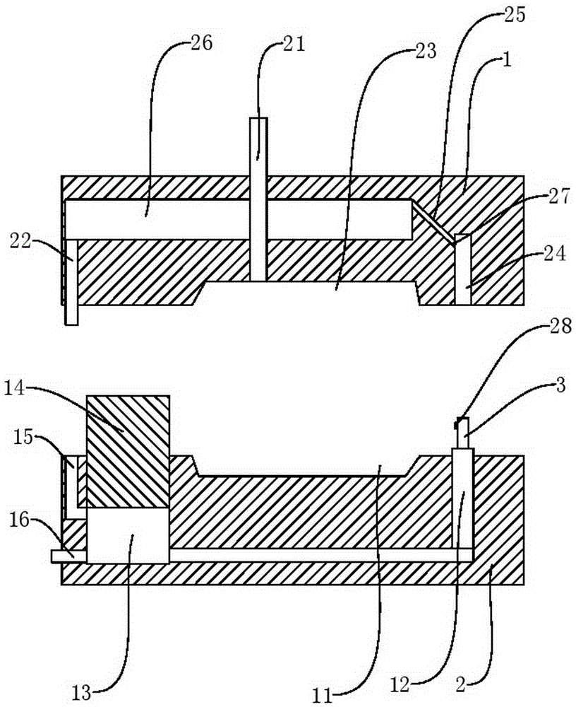
[0029] Basic as attached figure 1 Shown: mold with thermal insulation function, including:

[0030] The lower mold 2, the upper surface of the lower mold 2 is provided with a first molded surface 11, the surrounding of the first molded surface 11 is provided with a lower blind hole, the lower mold 2 is provided with a hydraulic chamber 13 filled with water, and the hydraulic chamber 13 is connected to the lower mold The blind hole communicates, the diameter of the cross section of the hydraulic chamber 13 is greater than the diameter of the cross section of the lower blind hole, the hydraulic chamber 13 is provided with a piston 14 slidingly connected with the hydraulic chamber 13, the piston 14 is exposed from the upper surface of the lower die 2, and the lower die 2 A liquid inlet 15 is provided on the top, and a one-way valve is provided in the liquid inlet 15. A drain pipe 16 is also provided on the lower mold 2. A drain valve is provided on the drain pipe 16. The drain pi...

Embodiment 2

[0034] Compared with Embodiment 1, the only difference is that the upper column 3 is in the shape of a truncated cone with a thick top and a thin bottom, the distance between the upper blind holes 24 is 5-10 mm, and the distance between the lower blind holes is the same as that of the upper blind holes 24. same.

Embodiment 3

[0036] Compared with Embodiment 1, the only difference is that there are at least two hydraulic chambers 13, and the hydraulic chambers 13 are all communicated with the lower blind hole, and the diameters of the cross-sections of all hydraulic chambers 13 are larger than the diameter of the lower blind hole cross-section, and the hydraulic pressure Pistons 14 that are slidably connected to the hydraulic chamber 13 are provided on the chambers 13 , and all of the pistons 14 are exposed from the upper surface of the lower mold 2 .


PUM


Abstract

The invention belongs to the field of mold manufacturing and specifically discloses a mold with a heat-insulating function. The mold comprises a lower mold, an upper mold and a heat-insulating column, wherein a first molded surface is arranged on the upper surface of the lower mold; lower blind holes are formed in the periphery of the first molded surface; a hydraulic chamber filled with water is arranged in the lower mold; the hydraulic chamber is communicated with the lower blind holes; the diameter of the cross section of the hydraulic chamber is greater than the diameters of the cross sections of the lower blind holes; a piston which is in sliding connection with the hydraulic chamber is arranged on the hydraulic chamber; the piston is exposed from the upper surface of the lower mold; a liquid feeding port is formed in the lower mold; a check valve is arranged in the liquid feeding port; the upper mold is matched with the lower mold; a feeding pipe, through which the materials can be fed, is arranged on the upper mold; a liquid draining pipe is arranged on the upper mold; a water valve is arranged on the liquid draining pipe; the liquid draining pipe right faces to the liquid feeding port; the heat-insulating column comprises an upper column and a lower column; the lower column is fixed in the lower blind holes; the upper column and the lower column are in sliding and sealing connection with each other. The invention provides the mold with the heat-insulating function, for solving the technical problems of inconvenience in use and energy waste when heat insulation is performed on the mold.

Description

technical field [0001] The invention relates to the field of mold manufacturing, in particular to a mold with heat preservation function. Background technique [0002] Mold, various molds and tools used in industrial production for injection molding, blow molding, extrusion, die-casting or forging forming, smelting, stamping and other methods to obtain the required products. In short, a mold is a tool used to shape an object. This tool is composed of various parts, and different molds are composed of different parts. It mainly realizes the processing of the shape of the article through the change of the physical state of the formed material. Known as the "Mother of Industry". [0003] The mold has a specific contour or cavity shape, and the application of the contour shape with a cutting edge can separate the blank according to the contour line shape (punching). Applying the shape of the inner cavity can make the blank obtain the corresponding three-dimensional shape. Th...

Claims


Application Information

Patent Timeline
IPC IPC(8): B29C45/26B29C45/78B29C45/73
CPCB29C45/26B29C45/73B29C45/78B29C2945/76531
Inventor 覃兵
Owner 绥阳县覃兵门窗有限公司
Why Eureka
Try Eureka