Lumber drying kiln

A technology for drying furnaces and wood, applied in drying, dryers, heating devices, etc., can solve problems such as boilers or pipelines are easy to form scale, reduce boiler thermal efficiency, and air thermal conductivity is small, so as to save drying time , cost reduction, and long service life

Inactive Publication Date: 2009-07-22
李祥文
View PDF6 Cites 0 Cited by
  • Summary
  • Abstract
  • Description
  • Claims
  • Application Information

AI Technical Summary

Problems solved by technology

[0003] The hot air stove first heats the air into hot air, and then circulates the hot air in the drying kiln through the air induction or blowing equipment, so as to achieve the effect of drying wood. However, when the hot air stove is used for wood drying, there are The following disadvantages: 1) If the heating of the hot blast stove is stopped, the temperature in the drying kiln will drop rapidly, and cracks will appear in the wood due to the large temperature difference in a short period of time, which will affect the drying quality; 2) The heat exchange medium of the hot blast stove is air, The thermal conductivity of the air is small, and the temperature of the hot air is low, which determines that when using this equipment to dry wood, the drying time is long, the temperature is not easy to control, and the production cost is high.
The cost of this kind of equipment is relatively low, but after long-term use, the inner wall of the boiler or pipeline is easy to form scale, which will greatly reduce the thermal efficiency of the boiler, and this problem is more obvious when used in areas with hard water quality

Method used


Image

  • Lumber drying kiln
  • Lumber drying kiln

Examples


Embodiment Construction

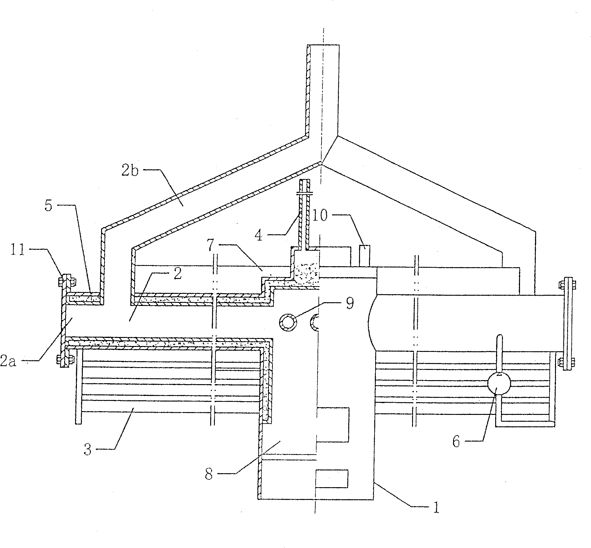
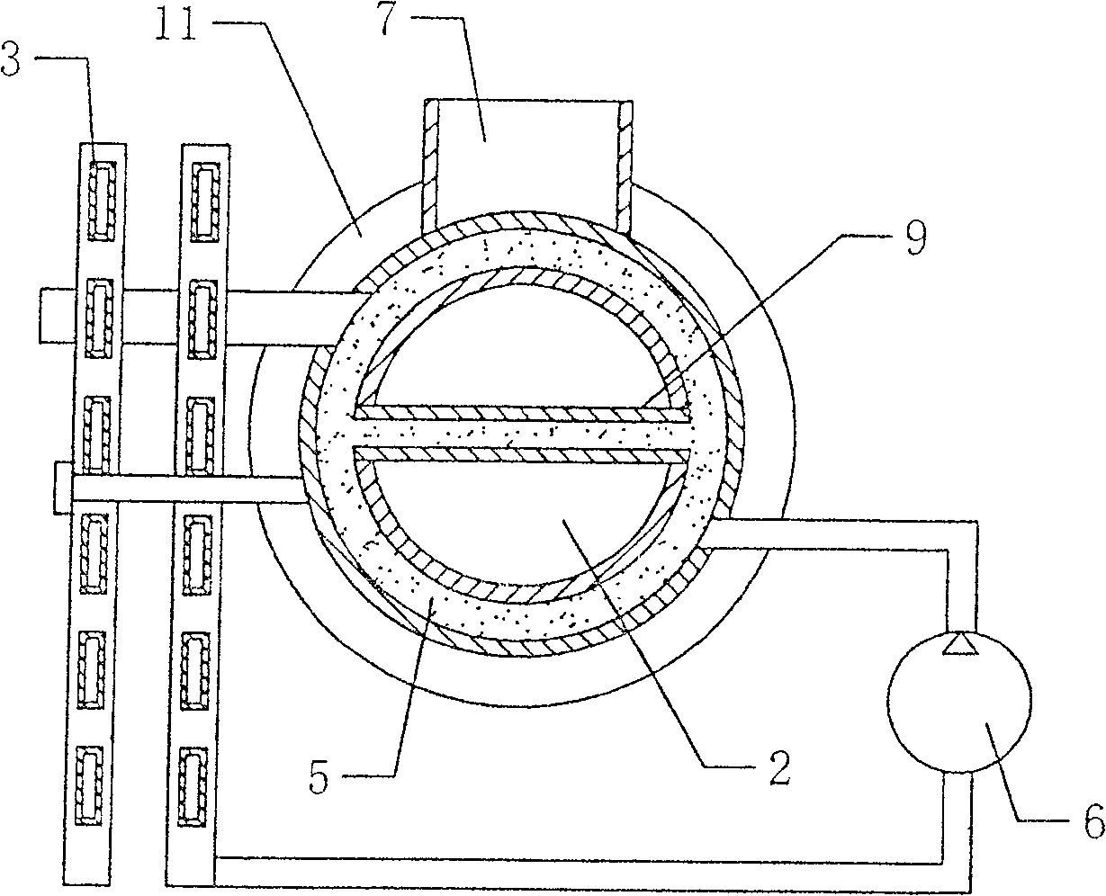
[0017] Such as figure 1 and figure 2 As shown, the wood drying furnace includes a furnace body 1, a flue 2 communicated with the combustion chamber 8 and the smoke outlet of the furnace body 1, the flue 2 is fixed on the outside of the furnace body 1, and the The flue 2 and the furnace body 1 are provided with a heat-conducting oil interlayer 5 connected to each other, and the heat-conducting oil interlayer 5 is provided with an expansion oil pipe 4 communicating with the atmosphere, which is used to circulate the heat-conducting oil in the heat-conducting oil interlayer 5. pump6.

[0018] The flue 2 includes a main flue 2a extending horizontally to both sides of the furnace body, an auxiliary flue 2b connected between the end of the main flue 2a and the smoke outlet, and the heat transfer oil interlayer 5 Wrapped on the outside of the main flue 2a and the furnace body 1, the main flue 2a can be set according to the size of the drying kiln. In this way, the heat transfer oi...


PUM


Abstract

The invention discloses a wood drying furnace, which comprises a furnace body, a flue communicated with a combustion chamber and a smoke outlet of the furnace body, the flue is fixed on the outside of the furnace body, and the flue and The furnace body is provided with a connected heat-conducting oil interlayer, and the heat-conducting oil interlayer is provided with an expansion oil pipe connected to the atmosphere, which is used for a hydraulic pump for circulating the heat-conducting oil in the heat-conducting oil interlayer; using heat-conducting oil as a medium, it can Obtain a higher drying temperature, and the temperature is easy to control, which greatly saves the drying time. Since the heat transfer oil interlayer is equipped with an open water collection tank, the amount of water can be increased or decreased according to the need, so that the humidity of the hot air can be controlled. The dried wood will not be cracked, deformed, discolored, and dried evenly, which improves the quality of the product. When the heat passes through the flue, it can be fully absorbed by the heat conduction oil in the flue interlayer, so that the heat can be fully utilized and improved. Heating speed, high thermal efficiency, saving fuel.

Description

technical field [0001] The invention relates to the technical field of drying equipment, in particular to a wood drying furnace. Background technique [0002] At present, there are mainly two types of equipment for drying wood in the drying kiln, one is a hot blast stove and the other is a steam boiler. [0003] The hot air stove first heats the air into hot air, and then circulates the hot air in the drying kiln through the air induction or blowing equipment, so as to achieve the effect of drying wood. However, when the hot air stove is used for wood drying, there are The following disadvantages: 1) If the heating of the hot blast stove is stopped, the temperature in the drying kiln will drop rapidly, and cracks will appear in the wood due to the large temperature difference in a short period of time, which will affect the drying quality; 2) The heat exchange medium of the hot blast stove is air, The thermal conductivity of the air is small, and the temperature of the hot ...

Claims


Application Information

Patent Timeline
Patent Type & Authority Patents(China)
IPC IPC(8): F26B23/10F26B23/02
Inventor 李祥文丁占科
Owner 李祥文
Why Eureka
Try Eureka