
Automobile collision protection device

A protective device and automobile technology, applied in vehicle parts, transportation and packaging, vehicle safety arrangements, etc., can solve problems such as economic property loss, vehicle scratches, vehicle and driver damage, etc., to alleviate the degree of damage and reduce damage degree, damage mitigation effect

Inactive Publication Date: 2017-02-22
SHANDONG JIAOTONG UNIV
View PDF9 Cites 6 Cited by
  • Summary
  • Abstract
  • Description
  • Claims
  • Application Information

AI Technical Summary

Problems solved by technology

However, only relying on the simple protection method of increasing the hardness only improves the hardness of the own vehicle when impacting. The existing anti-collision device cannot be reset after being deformed by the impact, thereby causing permanent deformation, and the existing anti-collision device The energy generated during the impact cannot be effectively used to buffer the impact force. Therefore, installing this traditional anti-collision device on the vehicle cannot effectively alleviate the vibration caused by the impact when the impact occurs, and there will still be impact on the vehicle and the driver. great damage
In addition, when the existing vehicle collides with other vehicles slightly or scratches, because the protective device of the vehicle is relatively hard, it will cause scratches to the vehicles that collide with each other, resulting in vehicle damage.
Before the insured vehicle arrives, the vehicle cannot be easily moved, which will not only cause traffic jams and delay the normal driving of the vehicle, but also need to repair the vehicle after the vehicle is damaged, resulting in economic and property losses. Obviously, the existing car protection devices cannot be more effective. satisfy people's demands

Method used


Image

  • Automobile collision protection device
  • Automobile collision protection device
  • Automobile collision protection device

Examples


Embodiment Construction

[0023] In order to clearly illustrate the technical features of this solution, the present invention will be described in detail below through specific implementation modes and in conjunction with the accompanying drawings.

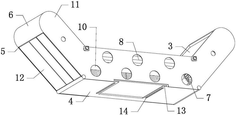
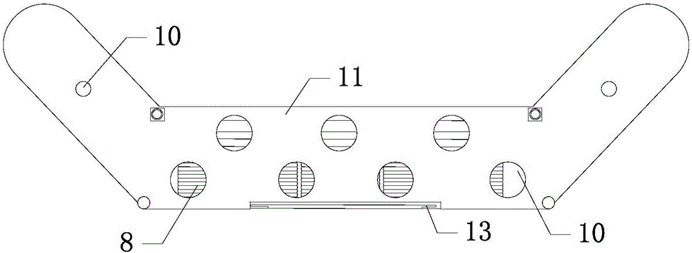
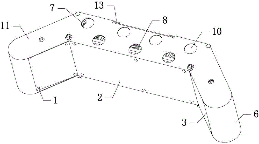
[0024] Such as Figure 1-6 As shown in , a car impact protection device includes a horizontally arranged fixed plate 2 with several threaded through holes 1 arranged on the edge, and a fixed side plate 3 arranged obliquely is symmetrically arranged on both sides of the fixed plate 2, The front side of the fixed plate 2 is provided with an outer baffle 4 parallel to the fixed plate 2, and an outer side plate 5 arranged parallel to the fixed side plate 3 is respectively symmetrically arranged on both sides of the outer baffle 4, and each outer side plate 5 The front end is movably connected with the two ends of the fixed plate 2 through the rotating shaft respectively, and the rear end of each outer plate 5 is respectively connected with the fixed side plat...


PUM


Abstract

The invention relates to the field of automobile protection equipment, in particular to an automobile collision protection device which comprises a fixed plate. Fixed side plates are symmetrically arranged on two sides of the fixed plate respectively, an outer retaining plate is arranged on the front side of the fixed plate, outer side plates are symmetrically arranged on two sides of the outer retaining plate respectively, the rear end of each outer side plate is connected with the corresponding fixed side plate through an arc-shaped rubber soft plate, and a plurality of anti-collision supporting devices are arranged around the front end face of the fixed plate. The automobile collision protection device is simple in structure, reasonable in design and simple to operate; when a collision occurs, the protection device can effectively play a role in retaining and protecting, and energy of collision force can be accumulated and stored to form a secondary protection layer; after the collision finishes, a collided position can be effectively restored, and damage to appearance of an automobile caused by the collision is reduced, so that needs of people are met more effectively, and the problems of the prior art are solved.

Description

[0001] Technical field: [0002] The invention relates to the field of automobile protection equipment, in particular to an automobile collision protection device. [0003] Background technique: [0004] As a means of transportation, automobiles have a wide range of applicable people in modern society. With the increase of vehicles, the number of various traffic accidents caused by vehicle collisions and scratches also presents an increasing trend. In order to reduce the degree of injury to the driver and the occupants of the car when traffic accidents such as collisions occur, the traditional method is to install an anti-collision device on the front and rear sides of the car, for example: add a bumper to the front and rear of the car, The function of the bumper is to increase the length of the front and rear sides of the car, which can enhance the impact resistance when external vehicles collide. This kind of bumper can increase the anti-collision ability of the car itself t...

Claims


Application Information

Patent Timeline
Patent Type & Authority Applications(China)
IPC IPC(8): B60R19/32B60R19/28B60R19/20
CPCB60R19/205B60R19/28B60R19/32
Inventor 山云霄
Owner SHANDONG JIAOTONG UNIV
Learn More