
Takeoff and landing system and method for fixed-wing unmanned aerial vehicle

A multi-rotor unmanned aerial vehicle and unmanned aerial vehicle technology, which is applied in the direction of unmanned aircraft, motor vehicles, aircraft, etc., can solve the problems of troublesome carrying, immature technology, complicated operation, etc., and achieve flexible take-off and landing, and reduce The effect of using cost and simple operation

Active Publication Date: 2017-02-22
天津凤凰智能科技有限公司
View PDF5 Cites 43 Cited by
  • Summary
  • Abstract
  • Description
  • Claims
  • Application Information

AI Technical Summary

Problems solved by technology

[0002] The takeoff and landing of common fixed-wing UAVs require a specific runway for them to taxi, but most of the civilian fields do not have enough take-off space, which limits the wide-scale promotion of fixed-wing UAVs in the civilian field to a certain extent.
[0003] With the development of UAV technology, fixed-wing UAV take-off methods such as vertical take-off, orbital catapult take-off, and hand-throwing have been derived, but these methods also have various defects, such as high production costs, Troublesome transportation, complicated operation, immature technology, etc. In addition, difficulty in recycling and landing is also a problem in the industry

Method used


Image

  • Takeoff and landing system and method for fixed-wing unmanned aerial vehicle
  • Takeoff and landing system and method for fixed-wing unmanned aerial vehicle
  • Takeoff and landing system and method for fixed-wing unmanned aerial vehicle

Examples


Embodiment 1

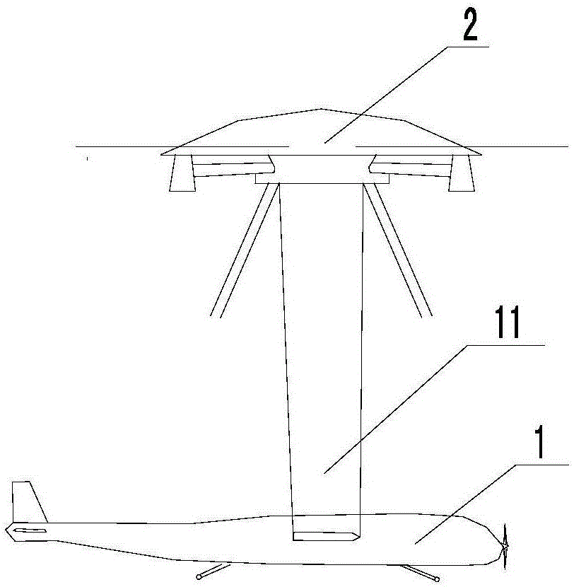
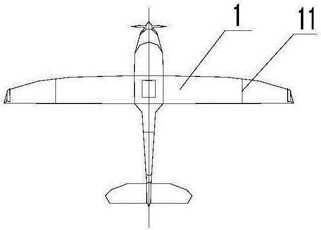
[0025] The invention provides a take-off and landing system for a fixed-wing unmanned aerial vehicle, such as Figure 1-2 As shown, it includes: a fixed-wing drone 1 and two multi-rotor drones 2, the fixed-wing drone 1 and the multi-rotor drone 2 are connected by a detachable connector, and the fixed The wings on both sides of the wing UAV are respectively provided with extension shafts 11 parallel to the central axis of the fuselage. The detachable connectors include protrusions arranged on the extension shafts 11. The protrusions are respectively provided, and mechanical grippers corresponding to the protrusions are evenly distributed below the multi-rotor UAV 2 with the center of gravity as the base point, so as to facilitate grasping by the grippers. The gripper is connected with the servo, and is controlled by the servo to close or open.

[0026] Through the detachable connector controlled by the server, when the fixed-wing UAV 1 takes off, two multi-rotor UAVs 2 take of...

Embodiment 2

[0032] The difference from Embodiment 1 is that the detachable connector includes a first electromagnetic part and a second electromagnetic part respectively arranged on the fixed-wing drone and the multi-rotor drone, and the first electromagnetic part and the second electromagnetic part The components are attracted to each other, and the magnetism of the first electromagnetic component and / or the second electromagnetic component is controlled by a servo. At least one of the first electromagnetic part and the second electromagnetic part is an electromagnet, and the other can be an electromagnet, or can be a metal that can be attracted by the electromagnet.

[0033] The detachable assembly composed of the first magnetic part and the second magnetic part, when connecting the fixed-wing drone and the multi-rotor drone, the alignment is more accurate, the connection is more convenient, and the servo operation is reduced. Difficulty; when separating the fixed-wing UAV 1 and the mul...

Embodiment 3

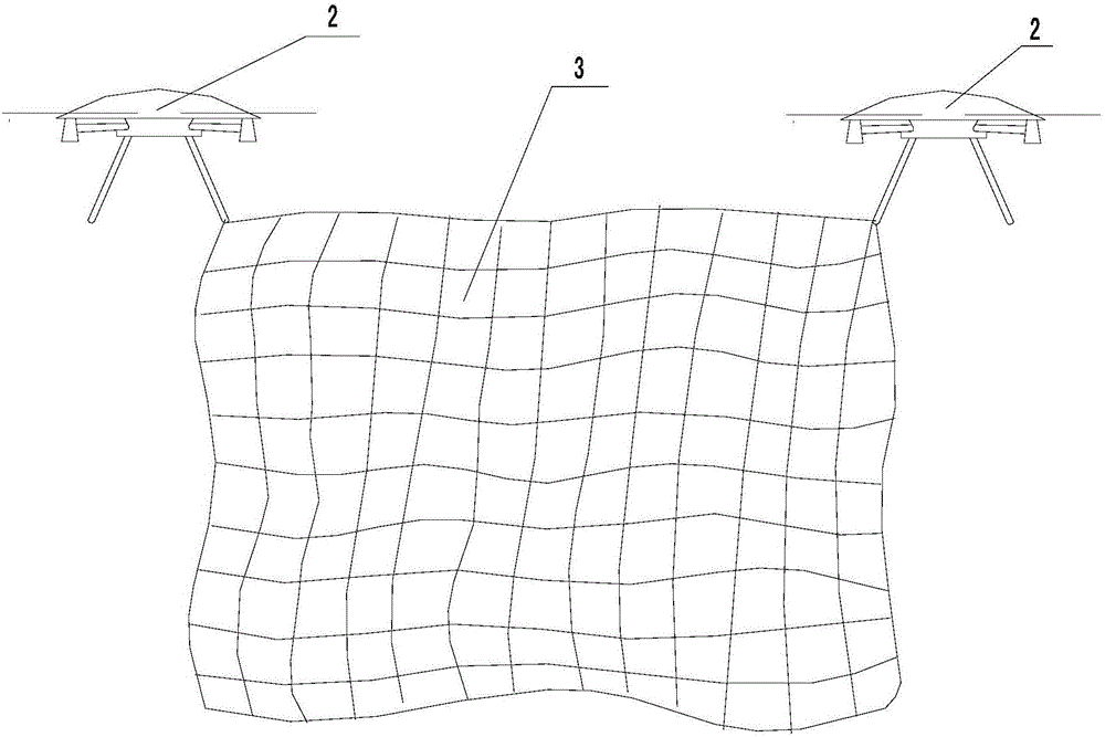
[0038] Different from Embodiment 1 and Embodiment 2, the take-off and landing system of the fixed-wing UAV also includes an interception net 3, such as Figure 1-3 As shown, the intercepting net 3 is arranged between at least two multi-rotor UAVs 2, and the edge of the intercepting net 3 is provided with a drawstring that can be pulled and retracted by the server. The setting of the intercepting net 3 solves the problem of high difficulty in connecting the fixed-wing UAV 1 and the multi-rotor UAV 2 that are in flight through detachable components when landing. The setting makes the landing method of the fixed-wing UAV 1 simpler and easier to operate.

[0039] Also provided is a method for take-off and landing of a fixed-wing UAV, in which the multi-rotor UAV 2 is detachably connected to the fixed-wing UAV 1 through a detachable connector, and the multi-rotor UAV 2 drives the fixed-wing UAV The UAV 1 takes off and accelerates in the air. When the fixed-wing UAV 1 rotates to th...


PUM


Abstract

The invention relates to the technical field of unmanned aircraft equipment, in particular to a takeoff and landing system and method for a fixed-wing unmanned aerial vehicle. The takeoff and landing system for the fixed-wing unmanned aerial vehicle comprises one or more fixed-wing unmanned aerial vehicles and one or more multi-rotor unmanned aerial vehicles, each of the fixed-wing unmanned aerial vehicles and the corresponding multi-rotor unmanned aerial vehicle are connected through a detachable connector, and the detachable connectors are closed or opened under the control of a servo. The invention further provides a takeoff and landing method for the fixed-wing unmanned aerial vehicle. Each of the multi-rotor unmanned aerial vehicles is connected with the corresponding fixed-wing unmanned aerial vehicle in a detachable manner through the corresponding detachable connector, each of the multi-rotor unmanned aerial vehicles drives the corresponding fixed-wing unmanned aerial vehicle to take off and accelerate in the air, and when each fixed-wing unmanned aerial vehicle rotates to a set rotation speed, the servo controls the detachable connectors to be disconnected, so that the no-slide takeoff of the fixed-wing unmanned aerial vehicles can be achieved. The arrangement of a ground takeoff runway is reduced, the use cost of the fixed-wing unmanned aerial vehicle is reduced, the operation is simple, and the takeoff and the landing are more flexible.

Description

technical field [0001] The invention relates to the technical field of unmanned aerial vehicle equipment, in particular to a system and method for taking off and landing of a fixed-wing unmanned aerial vehicle. Background technique [0002] The takeoff and landing of common fixed-wing UAVs require a specific runway for them to taxi, but most of the civilian fields do not have enough take-off space, which limits the wide-scale promotion of fixed-wing UAVs in the civilian field to a certain extent. . [0003] With the development of UAV technology, fixed-wing UAV take-off methods such as vertical take-off, orbital catapult take-off, and hand-throwing have been derived, but these methods also have various defects, such as high production costs, Problems such as troublesome transportation, complicated operation, immature technology, etc. In addition, difficulty in recycling and landing is also a problem in the industry. [0004] How to provide a flexible and easy-to-operate ta...

Claims


Application Information

Patent Timeline
IPC IPC(8): B64C39/00
CPCB64C39/00B64U30/00B64U10/25B64U70/00
Inventor 赵曙光
Owner 天津凤凰智能科技有限公司
Features
  • Generate Ideas
  • Intellectual Property
  • Life Sciences
  • Materials
  • Tech Scout
  • Unparalleled Data Quality
  • Higher Quality Content
  • 60% Fewer Hallucinations
Learn More