Auxiliary braking system for boarding bridge

An auxiliary braking and boarding bridge technology, applied in aircraft parts, ground installations, transportation and packaging, etc., can solve problems such as hidden safety hazards and easy inclination of boarding bridge passages, so as to ensure life safety, prevent inclination, improve The effect of safety features

Active Publication Date: 2017-02-22
中国民航技术装备有限责任公司
View PDF6 Cites 6 Cited by
  • Summary
  • Abstract
  • Description
  • Claims
  • Application Information

AI Technical Summary

Problems solved by technology

[0003] When the boarding bridge channel fails during the sliding process, and the boarding bridge channel is in the state of upward and downward, the traveling device will generate a backward or forward component force due to the gravity of the boarding bridge channel of tens of tons , which requires the walking device to have a large enough braking force to balance, the inside of the boarding bridge channel will be in an unstable state, and the boarding bridge channel is also prone to tilting, otherwise, the current boarding bridge channel does not have a stable and effective The braking system presents certain safety hazards for passengers, staff and boarding bridges

Method used


Image

  • Auxiliary braking system for boarding bridge
  • Auxiliary braking system for boarding bridge
  • Auxiliary braking system for boarding bridge

Examples


Embodiment 1

[0048] Embodiment one: if Figure 6 As shown, the brake bar 31 is a rack, and the brake member 32 is a gear meshed with the rack. The teeth of the rack face down and the back is fixed on the channel. The gear is located below the rack. During the stretching process, the switch valve 333 is in the open state, and the rack will drive the gear to rotate. During the braking process, the control system 2 closes the switch valve 333, the oil circuit block 332 stops circulation, the gear stops rotating and the rack is braked, and the phase is locked. movement between adjacent channels.

Embodiment 2

[0049] Embodiment two: if Figure 7 , Figure 8 As shown, the brake bar 31 is a rack, and the brake member 32 is a gear. The gear is arranged on one side of the rack. The tooth position of the rack faces the direction of the gear and engages with the gear. The rack is fixed on the channel through the mounting seat 38. .

Embodiment 3

[0050] Embodiment 3: The brake bar 31 and brake member 32 of Embodiment 3 can be improved based on the structure of Embodiment 2, such as Figure 7 , Figure 9 As shown, a guide rail 34 perpendicular to the telescoping direction of the channel is provided on the channel provided with the brake member 32, and a floating bracket 35 that can move left and right on the guide rail 34 is provided on the guide rail 34, and the brake member 32 It is arranged on the floating bracket 35, and the limiting member 36 is arranged on the floating bracket 35, and the limiting member 36 is used to adjust the stopper 32 and the braking member 32 under the condition that the adjacent channel deviates left and right during the expansion and contraction process. The occlusal gap between the strips 31, the limit member 36 is a pressure wheel and is fixed on one side of the floating bracket 35 through the eccentric shaft 37, the brake member 32 is arranged on the other side of the floating bracket 3...


PUM


Abstract

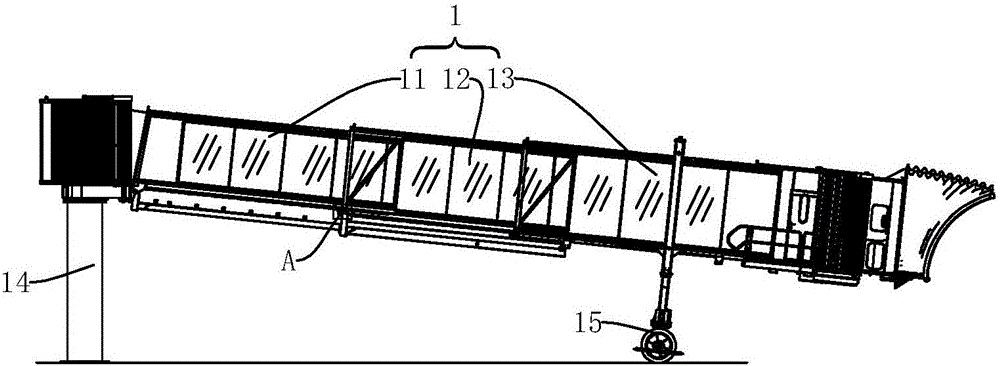
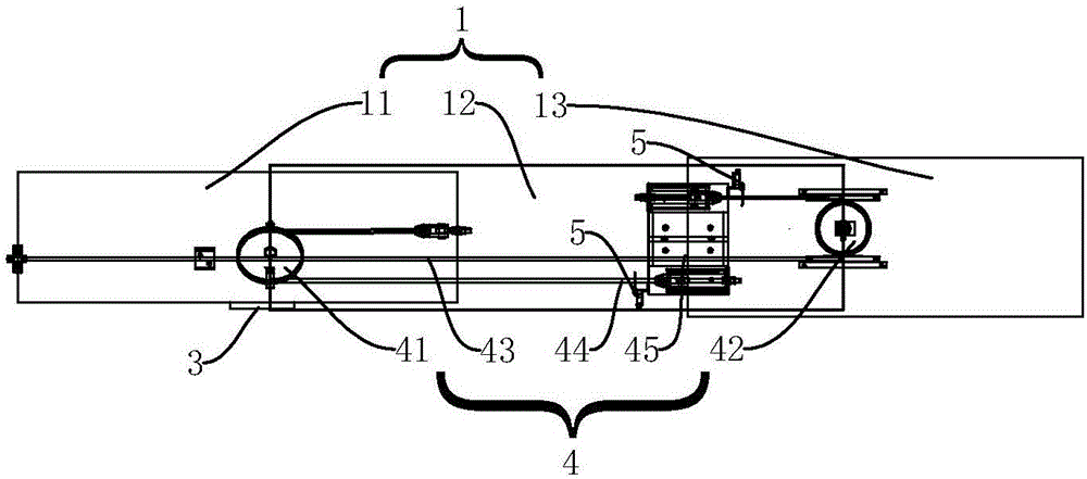
The invention discloses an auxiliary braking system for a boarding bridge. The auxiliary braking system for the boarding bridge comprises a telescopic boarding bridge passageway. The boarding bridge passageway is formed by at least two passageway bodies connected with each other in a sleeved mode. A passageway braking device is arranged between the adjacent passageway bodies of the boarding bridge passageway, and the input end of the passageway braking device is connected with the output end of a boarding bridge control system. The passageway braking device is used for stopping mutual movement between the passageway bodies in a locking mode after receiving a signal from the control system. Mutual movement is stopped in a locking mode by the passageway braking device, and braking of the out-of-control passageway bodies is effectively assisted. Therefore, the collapse accident caused by inclining of the boarding bridge passageway is prevented, the safety performance of the boarding bridge passageway is improved, and life security of staff and passengers is guaranteed.

Description

technical field [0001] The invention relates to a boarding bridge system, in particular to an auxiliary braking system for the boarding bridge. Background technique [0002] The boarding bridge is used to dock with the docked aircraft at the airport. The boarding bridge passage includes several mutually nested passages to form a retractable structure. At the same time, the inner and outer passages are stretched by rolling on the steel rails Movement, today's boarding bridge channels generally use two or three channels, and the three-channel boarding bridge channel is connected to the channel through the wire rope device under the drive of the walking device and drives each other to drive the telescopic movement of the boarding bridge channel , to pick up and park the aircraft. [0003] When the boarding bridge channel fails during the sliding process, and the boarding bridge channel is in the state of upward and downward, the traveling device will generate a backward or for...

Claims


Application Information

Patent Timeline
Patent Type & Authority Applications(China)
IPC IPC(8): B64F1/305
CPCB64F1/305
Inventor 胡克明张子健牛福维符平宣李伟东
Owner 中国民航技术装备有限责任公司
Why Eureka
Try Eureka