
Coil conveying device of heat shrinkage film wrapping machine

A conveying device and coating machine technology, applied in the directions of packaging, wrapping paper, wrapping paper shrinkage, etc., can solve the problems that affect the appearance of products, increase the production cost of enterprises, decrease the yield rate of products, etc., achieve stable clamping, improve Productivity and avoidance of rework

Active Publication Date: 2017-02-22
DONGGUAN JINGTIE MACHINERY
View PDF6 Cites 2 Cited by
  • Summary
  • Abstract
  • Description
  • Claims
  • Application Information

AI Technical Summary

Problems solved by technology

However, since the claws can only be stuck on the inner circle of the coil when extracting the coil, the packaging film covering the outside of the coil will inevitably become loose during the moving process, resulting in dislocation and disorder, and finally affecting the quality of the product during heat shrinkage. The appearance is beautiful, leading to a decrease in product yield and increasing the production cost of the enterprise

Method used


Image

  • Coil conveying device of heat shrinkage film wrapping machine
  • Coil conveying device of heat shrinkage film wrapping machine
  • Coil conveying device of heat shrinkage film wrapping machine

Examples


Embodiment Construction

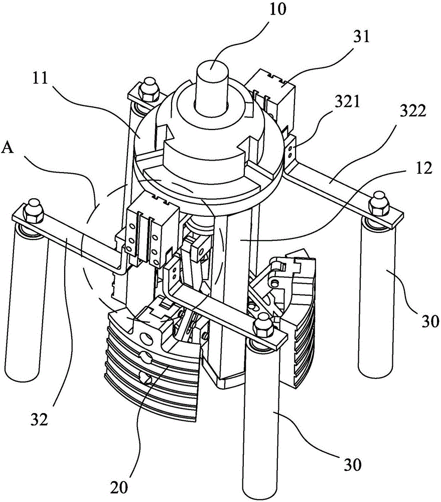
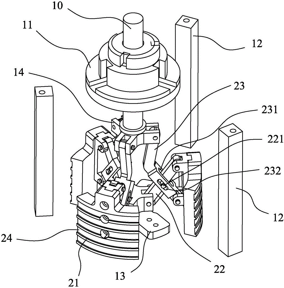
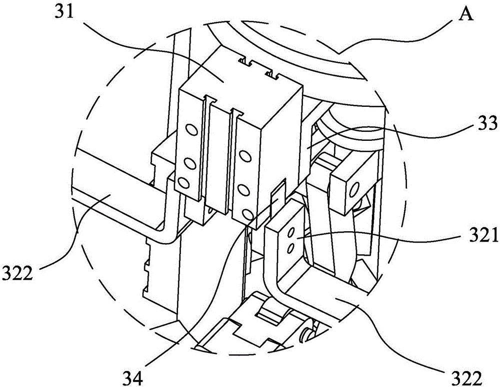
[0030] Please refer to Figure 1-3 As shown, a coil delivery device of a heat shrink wrapping machine includes a claw mechanism for clamping the inner circle of the coil and a clamping mechanism for clamping the outer circle of the coil. The claw mechanism includes a plurality of annular The distributed claws 20, the push rod 10 that drives each claw 20 to open and close in the radial direction, and the first drive element that drives the push rod 10 to move up and down, the clamping mechanism includes a plurality of rings distributed outside the claws 20 The clip bar 30 and the second driving element 31 that drives the clip bar 30 to flip open and close.

[0031] The claw mechanism also includes a push rod mounting seat 11, a claw connecting seat 14, a claw base 13 and a plurality of support rods 12 connected between the push rod mounting seat 11 and the claw base 13. The seat 11 is provided with a shaft hole that is compatible with the push rod 10, and the push rod 10 is mo...


PUM


Abstract

The invention discloses a coil conveying device of a heat shrinkage film wrapping machine. The coil conveying device comprises a clamping claw mechanism used for clamping the inner circle of a coil, and a film clamping mechanism used for clamping the outer circle of the coil. The clamping claw mechanism comprises a plurality of clamping claws annularly distributed, a push rod driving the clamping claws to be opened and closed in the radial direction at the same time, and a first driving element driving the push rod to move up and down. The film clamping mechanism comprises a plurality of clamping rods annularly distributed on the outer sides of the clamping claws, and second driving elements driving the clamping rods to be overturned, opened and closed. During work, the first driving element drives the push rod to move downwards, the push rod drives the clamping claws to be opened outwards in the radial direction to be clamped on the inner circle of the coil, and the second driving elements drive the clamping rods to be overturned downwards to be clamped to the outer circle of the coil. According to the coil conveying device, the clamping rods are arranged on the outer sides of the clamping claws, a packaging film wrapping the coil is clamped and positioned through the clamping rods, the situation of dislocation in the moving process cannot happen, the packaging film is constantly kept to wrap the coil intactly, and therefore the attractiveness of a finished coil packaging product is improved.

Description

technical field [0001] The invention relates to the technical field of coil coating equipment, in particular to a coil conveying device of a heat shrink coating machine. Background technique [0002] In the wire production process, according to market demand, the wire needs to be heat-shrinkable after being coiled. At present, in the packaging process, the coil is mainly transported by a claw that can be stuck on the inner circle of the coil. This claw can easily extract and put down the coil and improve the packaging efficiency of the wire. However, since the claws can only be stuck on the inner circle of the coil when extracting the coil, the packaging film covering the outside of the coil will inevitably become loose during the moving process, resulting in dislocation and disorder, and finally affecting the quality of the product during heat shrinkage. The aesthetics of the appearance will lead to a decline in product yield and increase the production cost of the enterpr...

Claims


Application Information

Patent Timeline
Patent Type & Authority Applications(China)
IPC IPC(8): B65B35/16B65B53/02B65B25/24
CPCB65B25/24B65B35/16B65B53/02
Inventor 谭良明程泉
Owner DONGGUAN JINGTIE MACHINERY
Learn More