Robot gripper for automatically gripping horns
A robot hand and robot technology, applied in packaging, etc., can solve problems such as insufficient speed and efficiency, increased labor costs, and inability to achieve accurate positioning, so as to achieve the effects of improving efficiency, improving production efficiency, and saving labor and labor
- Summary
- Abstract
- Description
- Claims
- Application Information
AI Technical Summary
Problems solved by technology
Method used
Image
Examples
Embodiment 1
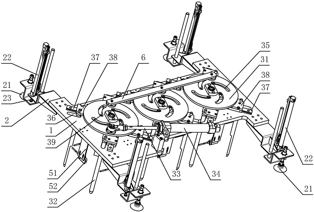
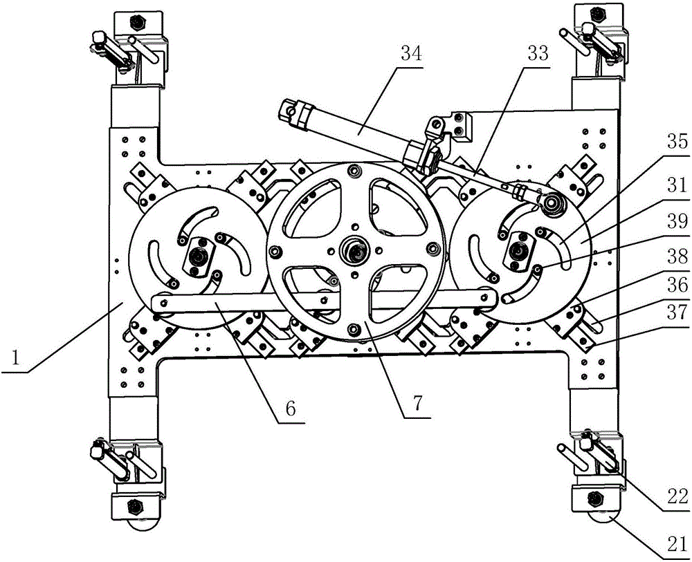
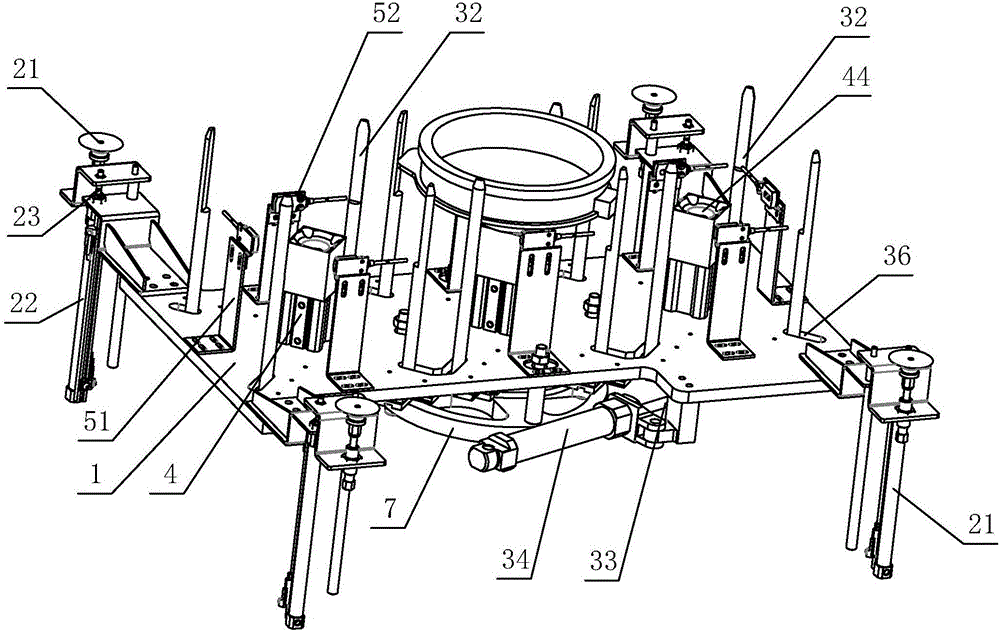
[0025] refer to figure 1 , a horn automatically grabbing the robot claw, the claw is a detachable structure arranged on the top of the robot, the horn automatically grabbing the robot claw includes a bracket plate 1, an adsorption structure 2, and a magnetic attraction structure 4, preferably, A tensioning structure 3 is also included. refer to Figure 6 , the structure of the present invention is the claw part of the robot, which plays the roles of grabbing, carrying, positioning and counting.
[0026] refer to Figure 5 , the adsorption structure 2 includes a suction cup 21 and a second push rod 22 that pushes the adsorption structure 2 to expand and contract. In the sleeve rod 23. Preferably, the suction cups 21 are arranged at the four corners of the support plate 1. Under the control of the control cabinet, the robot rotates above the paper pallet, and the second set of rods 23 pushes the second pusher under the action of the cylinder. The rod 22 moves downward, driv...
Embodiment 2
[0032] Embodiment 2: A plurality of first sets of rods 34 are arranged on the support plate 1, any one of the first sets of rods 34 drives the first push rod 33 to reciprocate, and any one of the first push rods 33 is hinged on the groove plate 31 , that is, each grooved plate 31 is connected to a first push rod 33, and the rest of the structure is the same as that of Embodiment 1. This setting can realize that a first push rod 33 drives a grooved disc 31 to rotate, and then drives any tension structure 3 to be in an expanded state or a contracted state; this can realize individual control of each tension structure 3 to grasp or release independently The number of horns and claws can be the same or different each time.
Embodiment 3
[0033] Embodiment 3: There are one, two or more tensioning structures 3 , preferably, there are three tensioning structures 3 . The greater the number of tensioning structures 3, the greater the number of grabs can be ensured, and the higher the efficiency. However, when there are too many grabs, the load will be larger, and it will be more difficult to handle and adjust after a fault occurs. Therefore, a better implementation For example, there are three tension structures 3 . The number in this embodiment is not limited to three, and more than three tension structures 3 also belong to the protection scope of the present invention.
[0034] A driven rod 6 that simultaneously hinges a plurality of grooved disks 31 is arranged between a plurality of grooved disks 31, and a first push rod 33 drives the grooved disk 31 hinged thereto, and the grooved disk 31 drives the driven rod 6 to rotate, The driven rod 6 drives any other grooved disc 31 to move. A first push rod 33 is used...
PUM
 Abstract
Description
Claims
Application Information
 - R&D
- Intellectual Property
- Life Sciences
- Materials
- Tech Scout
- Unparalleled Data Quality
- Higher Quality Content
- 60% Fewer Hallucinations
Browse by: Latest US Patents, China's latest patents, Technical Efficacy Thesaurus, Application Domain, Technology Topic, Popular Technical Reports.
© 2025 PatSnap. All rights reserved.Legal|Privacy policy|Modern Slavery Act Transparency Statement|Sitemap|About US| Contact US: help@patsnap.com


