Power roller conveyor

A technology of conveyors and rollers, which is applied in the field of conveyors using rollers, can solve problems such as safety accidents, slippage, parts collision, extrusion, etc., and achieve the effect of protecting surface quality

Active Publication Date: 2017-02-22
CHONGQING KEBEN TECH
View PDF6 Cites 3 Cited by
  • Summary
  • Abstract
  • Description
  • Claims
  • Application Information

AI Technical Summary

Problems solved by technology

The transmission speed of the parts is related to the friction between the transmission surface of the cylindrical roller and the parts to be transported. If the friction is too small, the transmission will easily slip, causing parts to collide, squeeze, or even cause safety accidents.
[0003] On the other hand, the relative position of the roller table of the commonly used roller conveyor is fixed, but in actual production, it is necessary to adjust the roller table to achieve different conveying target positions

Method used


Image

  • Power roller conveyor
  • Power roller conveyor
  • Power roller conveyor

Examples


Embodiment Construction

[0031] The implementation of the present invention will be illustrated by specific specific examples below, and those skilled in the art can easily understand other advantages and effects of the present invention from the contents disclosed in this specification.

[0032] Below in conjunction with accompanying drawing and embodiment the present invention will be further described:

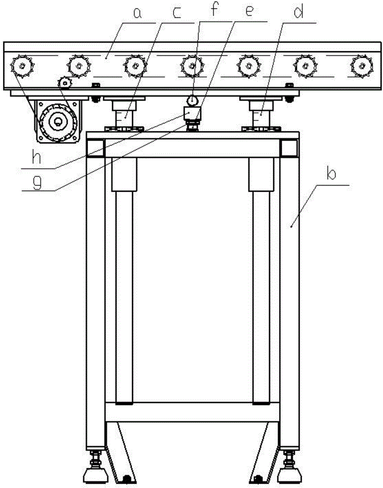
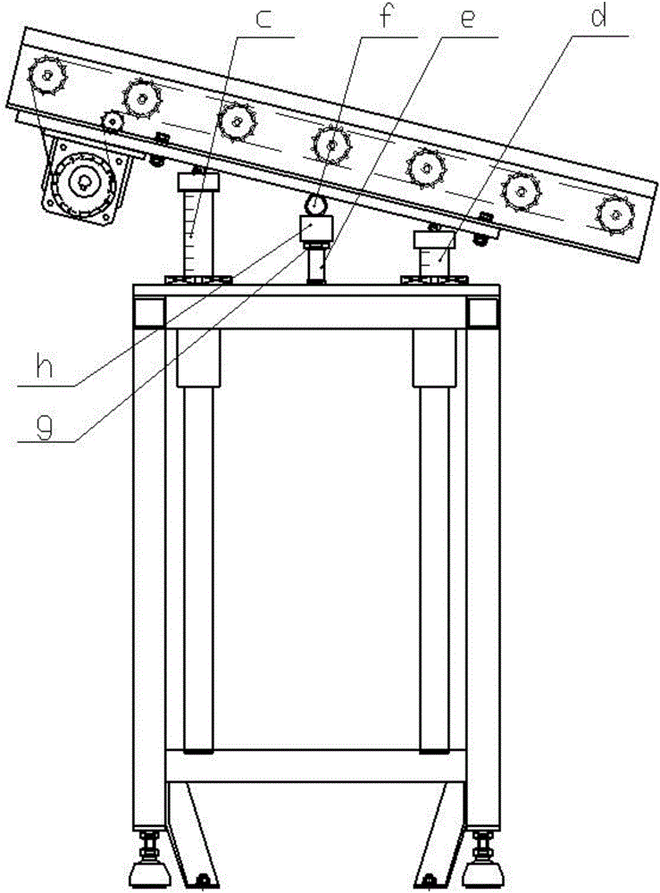
[0033] like figure 1Shown in -6, a kind of roller conveyer comprises frame b and roller table a, and described roller table a is positioned on frame b; Described frame b is vertically provided with two hydraulically telescopic shafts, respectively It is the left hydraulic telescopic shaft c and the right hydraulic telescopic shaft d, the top of each hydraulic telescopic shaft is hinged with the bottom surface of the roller table a, a screw e is vertically arranged between the two hydraulic telescopic shafts, and a movable screw e is arranged above the nut g of the screw e The steel pipe h that is...


PUM


Abstract

The invention discloses a roller conveyor including a rack and a roller, the roller is on the rack; the frame is provided with two hydraulic telescopic shafts. The top of each hydraulic telescopic shaft is hinged with the bottom surface of the roller table. The two hydraulic telescopic shafts are provided with a screw rod. The upper part of the screw nut is provided with a steel pipe sheathed on the screw rod. The top end of the steel pipe is provided with a supporting shaft which is parallel with the bottom surface of the roller table and is perpendicular to the conveying direction of the roller table. The roller comprises a rotating shaft and a first roller sheathed on the shaft. Second rollers are arranged between the first roller and the rotating shaft, Second rollers are provided with a plurality of blind holes. A spring is arranged in the blind hole, and the spring extends into the bottom end of the rolling body. Pluralities of grooves are arranged on the inner wall of the first roller. The bottom of each groove is provided with a plurality of through holes, and the through hole is a single page hyperboloid surface with two big ends and a small middle. The roller conveyor can flexibly lift and adjust the transmission angle position and also be used to select the smooth cylindrical surface or the rough cylindrical surface to transfer the corresponding parts.

Description

technical field [0001] The invention belongs to the technical field of material conveying, and in particular relates to a conveyor adopting a roller table. Background technique [0002] Automatic transportation is widely used in production and life. Usually, when transferring parts or final output products, the discharge machine is used to discharge the material. The discharge machine is a common name for a type of equipment that outputs parts and goods. Roller conveyors are common in mechanical processing. , it mainly includes a roller table. The so-called roller table is the main equipment for transporting rolled pieces in the rolling workshop. Its weight accounts for about 40% of the total weight of the equipment in the rolling workshop. It is the most used equipment in the rolling workshop. Rolled pieces enter and exit the heating furnace, are reciprocally rolled on the rolling mill, and are transported to the finishing process after rolling, etc., are all completed by t...

Claims


Application Information

Patent Timeline
Patent Type & Authority Applications(China)
IPC IPC(8): B65G41/00
CPCB65G41/002
Inventor 朱兴德
Owner CHONGQING KEBEN TECH
Why Eureka
Try Eureka