
Portable non-power-source microfluidic cell separation chip

A technology for separating chips and power sources, applied in the direction of sterilization methods, methods of supporting/immobilizing microorganisms, biochemical equipment and methods, etc., to achieve the effect of convenient processing and manufacturing and low manufacturing cost

Active Publication Date: 2017-02-22
HUAZHONG UNIV OF SCI & TECH
View PDF3 Cites 14 Cited by
  • Summary
  • Abstract
  • Description
  • Claims
  • Application Information

AI Technical Summary

Problems solved by technology

[0008] The above methods can achieve efficient particle separation and cell separation, but they all need to provide an additional power source to drive the sample flow, which is not suitable for applications in remote areas far from hospitals

Method used


Image

  • Portable non-power-source microfluidic cell separation chip
  • Portable non-power-source microfluidic cell separation chip

Examples


Embodiment Construction

[0028] In order to make the object, technical solution and advantages of the present invention clearer, the present invention will be further described in detail below in conjunction with the accompanying drawings and embodiments. It should be understood that the specific embodiments described here are only used to explain the present invention, not to limit the present invention. In addition, the technical features involved in the various embodiments of the present invention described below can be combined with each other as long as they do not constitute a conflict with each other.

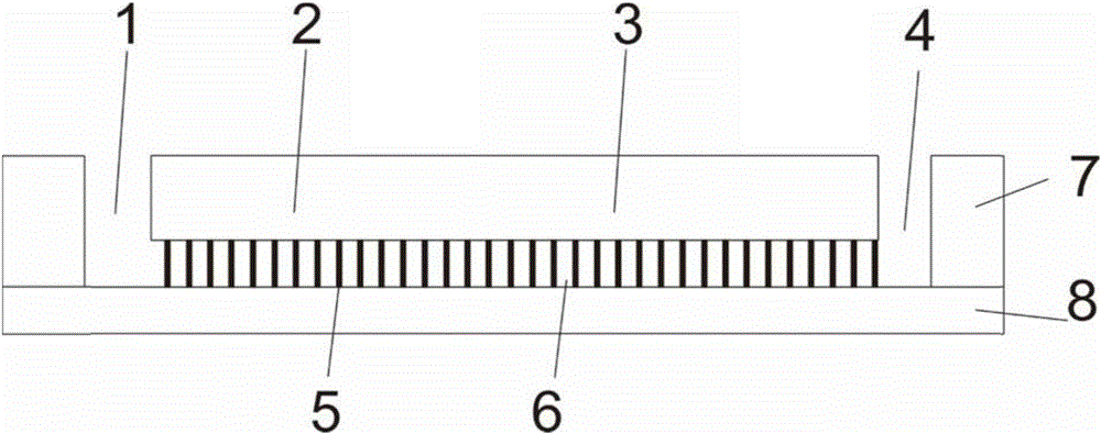
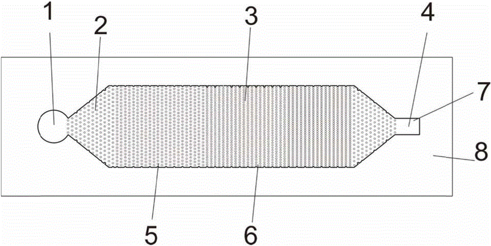
[0029] figure 1 It is a side view of a portable non-powered microfluidic cell separation chip in an embodiment of the present invention; figure 2 yes figure 1 The top view of the cell separation chip in the middle, combined with the two figures, it can be seen that the portable microfluidic cell separation chip without power source of the present invention includes a base 7 and a cover sheet ...


PUM

PropertyMeasurementUnit
heightaaaaaaaaaa
diameteraaaaaaaaaa
distanceaaaaaaaaaa

Abstract

The invention discloses a portable non-power-source microfluidic cell separation chip. The chip comprises a substrate and a cover plate covering the substrate. The substrate comprises an input opening, a flow guiding region, a separating region and a collection opening in sequence from the input end to the output end. The input opening is used for dropwise adding body fluid with cells to be separated, the flow guiding region is used for guiding the body fluid with the cells to be separated to the separating region, the separating region is used for separating the cells, the collection opening is used for collecting the cells separated out in the separating region, the flow guiding region and the separating region are provided with a plurality of regularly-distributed columnar protrusions, the height of the columnar protrusions is 15-50 micrometers, the diameter of the columnar protrusions is 10-50 micrometers, the intervals between the columnar protrusions in the flow guiding region are 15-25 micrometers, and the intervals between the columnar protrusions in the separating region are 2-15 micrometers. The cell separation chip is powered through the capillary action force, does not need a power source, and is convenient to carry and manufacture and easy to operate and use.

Description

technical field [0001] The invention belongs to the field of microfluidic chips, and in particular relates to a cell separation chip without a power source based on a filtration method. Background technique [0002] In recent decades, microfluidic technology has developed rapidly in analytical chemistry, biological detection, clinical medicine and other application fields, and has replaced some traditional application methods. For example, traditional cell analysis and sorting generally use flow cytometry, which is fast, high-precision, and accurate, but requires complex and expensive equipment, and the detection cycle is long, so it is only suitable for large hospitals and laboratories . [0003] Microfluidics uses integrated and miniaturized microfluidic chips, which can quickly detect and analyze samples in a short time with only a small amount of samples. Compared with traditional methods, the whole process is faster, more efficient and environmentally friendly. [00...

Claims


Application Information

Patent Timeline
Patent Type & Authority Applications(China)
IPC IPC(8): C12M1/12
CPCC12M23/16
Inventor 吴志刚刘振华徐文超张硕彭鹏张攀邓杰
Owner HUAZHONG UNIV OF SCI & TECH
Learn More