Sewer structure

A gutter, the same technology, applied in the field of gutter structure, can solve the problems of increasing the cable length, affecting the process flow, etc., achieving the effect of simple structure, reasonable design, and eliminating the need for line planning and redesign

Inactive Publication Date: 2017-02-22
税显治
View PDF0 Cites 0 Cited by
  • Summary
  • Abstract
  • Description
  • Claims
  • Application Information

AI Technical Summary

Problems solved by technology

In the past, in order to solve this problem, the design is to avoid the formation of the gutter to enclose a certain area and leave an exit, but this method usually affects the smooth process flow to a certain extent and increases the length of the cable

Method used


Image

  • Sewer structure

Examples


Embodiment

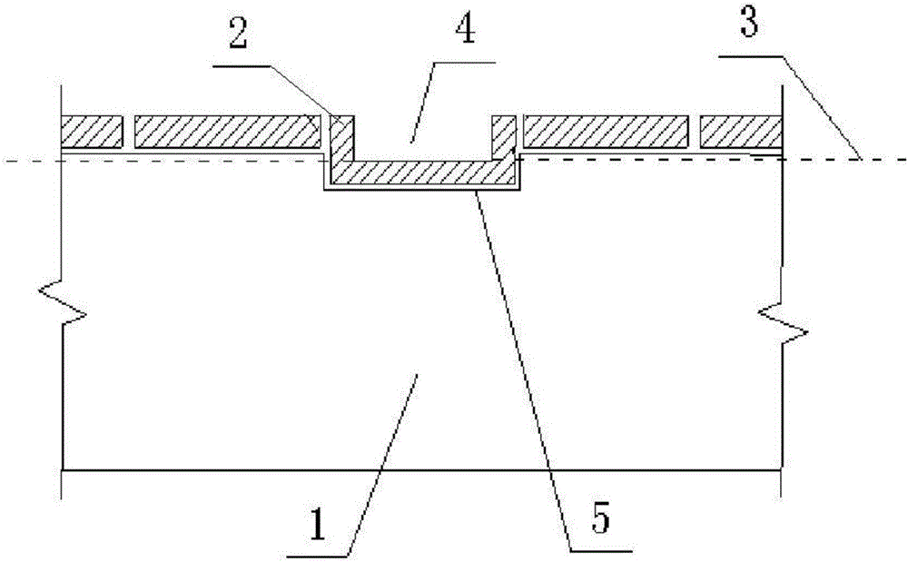
[0012] Such as figure 1 As shown, a gutter structure includes a gutter body 1 buried under the ground 3 and a gutter cover 2 arranged on the top of the gutter body 1 , and the top of the side wall of the gutter body 1 is higher than the ground 3 on both sides. The gutter cover 2 is provided with a rainwater aqueduct 4 communicating with the ground 3 on both sides of the gutter body 1 , and the inner bottom surface of the rainwater aqueduct 4 is on the same level as the ground 3 on both sides of the gutter body 1 . A groove 5 corresponding to the rainwater aqueduct 4 is provided on the top of the side wall of the gutter main body 1 . The cross-section of the rainwater aqueduct 4 is in the shape of a "mouth" with an upper opening, which can maximize the flow of rainwater through the rainwater aqueduct 4, reducing the possibility of excessive rainwater flow and causing water accumulation.

[0013] In normal use, when rainwater is discharged from the factory building to the gutte...


PUM


Abstract

The invention discloses a sewer structure. The sewer structure comprises a sewer main body buried underground and a sewer cover plate arranged at the top of the sewer main body; the top of the side wall of the sewer main body is higher than the ground on two sides of the sewer main body; a rain aqueduct is formed in the sewer cover plate and communicated with the ground on two sides of the sewer main body; the inner bottom surface of the rain aqueduct and the ground on two sides of the sewer main body are positioned on the same plane; and a groove corresponding to the rain aqueduct is formed in the top of the side wall of the sewer main body. The sewer structure is simple in structure and reasonable in design, rain aqueducts are formed in the sewer every certain distance, and the interval between two adjacent rain aqueducts is preferably 20m so that rain in the field can flow smoothly, and field waterlogging cannot be caused due to large-scale application of the sewer, and the problem of re-designing the route planning of sewers can be avoided.

Description

technical field [0001] The invention relates to a gutter structure. Background technique [0002] With the continuous expansion of the scale of modern factories, the number of cables has increased sharply, and the use of gutters in the factory area has become more and more frequent. The large-scale use of sewers has also brought a series of problems, and affecting the drainage of the factory site is one of the more difficult problems to solve. The rainwater in the factory area is usually drained to the road through the slope of the site, and then drained away through the rainwater drainage system of the road. If the elevation of the top of the gutter set on the factory site is at the same level as the ground elevation on both sides of the gutter, the rainwater on the site will flow into the gutter through the inspection hole on the gutter cover. In order to avoid backflow of rainwater on the site, the height of the side wall of the gutter is generally designed to be about ...

Claims


Application Information

Patent Timeline
Patent Type & Authority Applications(China)
IPC IPC(8): E03F3/04
CPCE03F3/046
Inventor 税显治
Owner 税显治
Why Eureka
Try Eureka