
A kind of cam mechanism of fingerprint lock

A cam mechanism and fingerprint lock technology, which is applied in the field of anti-theft locks, can solve the problems of lack of permeability of the key hole of the lock cylinder, inconvenient removal of foreign objects in the key hole, and scattered structural layout.

Active Publication Date: 2018-07-06
重庆桐雨石科技有限公司
View PDF6 Cites 0 Cited by
  • Summary
  • Abstract
  • Description
  • Claims
  • Application Information

AI Technical Summary

Problems solved by technology

Although the above scheme has achieved the expected goal, after all, the original permeability of the key hole of the lock cylinder is gone, it is not easy to remove foreign objects in the key hole, and the structural layout is relatively scattered

Method used


Image

  • A kind of cam mechanism of fingerprint lock
  • A kind of cam mechanism of fingerprint lock
  • A kind of cam mechanism of fingerprint lock

Examples


Embodiment Construction

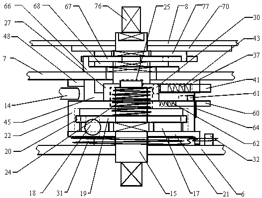
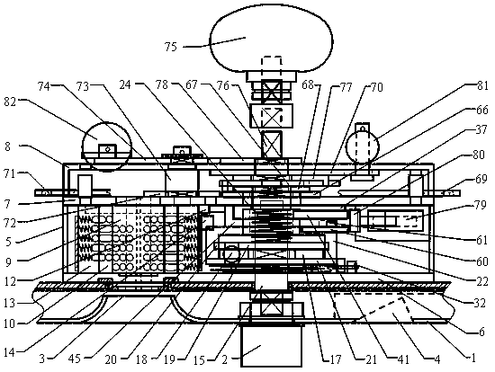
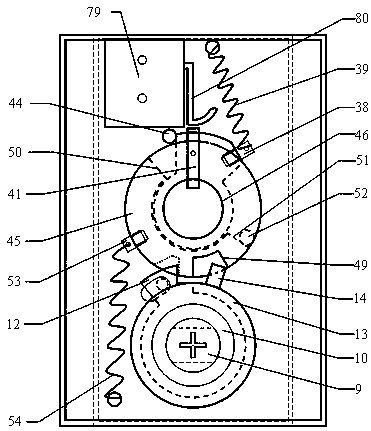
[0042] Combine below Figure 1 to Figure 22 The present invention is further described.

[0043] (1) Component structure:

[0044] Such as figure 2 As shown, a full set of fingerprint lock mainly includes a fingerprint recognition system, a lock outer panel 1, a handle 2, a lock body 5, a main bolt 81 and a dead bolt 82. The upper part of the lock outer panel 1 is provided with a fingerprint collector 4, the middle part of the lock outer panel 1 is equipped with a handle 2, and the lower part of the lock outer panel 1 is provided with a key jack center 3.

[0045] Such as figure 1 , 2 , 3, and 22, the lock body 5 includes an anti-skid plate 6, a back plate 7, a buckle cover 8, a lock cylinder 9, an inner rotating ring 10, an outer rotating ring 13, a dial ring 11, a cam mechanism, and a forward drive plate 66 , reverse drive plate 68, swing rod 67, main pull plate 69, T-shaped rotating plate 70, auxiliary pull plate 71, main linkage piece 72, linkage shaft 73, auxiliary ...


PUM


Abstract

The invention discloses a cam mechanism for a fingerprint lock, and relates to the field of anti-theft locks. The mechanism is mainly composed of a cam shaft, a moment limiter, a driven ring, a cam ring, a thumbwheel, a main clutch and a subsidiary clutch. The cam mechanism is located in the lock body of the fingerprint lock, one end is connected to a handle, the other end is connected to drive parts of a lock plunger and a spring bolt and used for transmitting, controlling or stopping rotary motion of the handle, fingerprint identification unlocking, key inserting key unlocking and locking operation are all achieved by the same handle, and the handle can idle when strong wrenched. As an alternative solution of the prior art, the subsidiary clutch of the cam mechanism is arranged between the driven ring and the cam ring, and the way to drive the subsidiary clutch through a key is abandoned. The main clutch is still arranged between the thumbwheel and the driven ring, a motor can meanwhile drive two clutches to close, the structure is more compact, stability and safety are more outstanding, and original permeability of a lock core is restored.

Description

technical field [0001] The invention relates to the field of anti-theft locks, in particular to a cam mechanism of a fingerprint lock. Background technique [0002] The structure of the fingerprint lock generally includes the outer panel of the lock, the inner panel of the lock, the handle, the lock body, the spare mechanical key, the fingerprint identification system or the password identification system, and the motor clutch or electromagnetic clutch under its control. [0003] Under normal circumstances, the fingerprint lock completes the locking action by rotating the handle in the opposite direction (that is, lifting the handle), or automatically locks when the door is closed; when the fingerprint or password is used to unlock the lock, after the fingerprint identification or password identification is correct, the motor clutch Or the electromagnetic clutch is closed, and the unlocking is completed by rotating the handle in the positive direction. When the fingerprint ...

Claims


Application Information

Patent Timeline
Patent Type & Authority Patents(China)
IPC IPC(8): E05B47/00E05B15/00E05B49/00
CPCE05B15/0013E05B15/004E05B47/0012E05B49/00E05B2047/0024E05B2047/0026
Inventor 吕雪寒曹俊标叶延亮
Owner 重庆桐雨石科技有限公司
Learn More