Shaft type emergency exit structure system of intercity railway tunnel

An emergency exit, intercity railway technology, applied in tunnels, mines/tunnel ventilation, safety devices, etc., can solve the problems of difficult construction and maintenance, waste of investment, blank design methods for shaft-type emergency exits, etc., to save tunnel construction And the effect of operation and maintenance cost, complete facilities and simple structure

Inactive Publication Date: 2017-02-22
SOUTHWEST JIAOTONG UNIV +2
View PDF6 Cites 4 Cited by
  • Summary
  • Abstract
  • Description
  • Claims
  • Application Information

AI Technical Summary

Problems solved by technology

Due to the constraints of the tunnel environment, construction auxiliary tunnels and other conditions, the emergency exits for evacuation generally adopt the structure of flat guides, horizontal holes, and inclined shafts, and vertical shafts are rarely used as emergency exits. Regarding the design method of shaft emergency exits Research is also basically blank
Especially with the construction of a large number of intercity railways, there will be a large number of construction shafts. If they are not utilized and specially excavated inclined shafts or horizontal holes are used as emergency exits, it will inevitably cause waste of investment and excavate horizontal holes in urban areas. Or the inclined shaft also has the problem of difficulty in construction and later maintenance

Method used


Image

  • Shaft type emergency exit structure system of intercity railway tunnel
  • Shaft type emergency exit structure system of intercity railway tunnel
  • Shaft type emergency exit structure system of intercity railway tunnel

Examples


Embodiment Construction

[0027] The present invention will be further described below in conjunction with specific embodiment, and specific embodiment is a further description of the principle of the present invention, does not limit the present invention in any way, and the same or similar technologies as the present invention do not exceed the protection scope of the present invention.

[0028] combined with Figure 1 to Figure 4 .

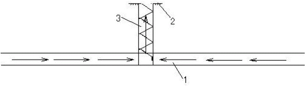
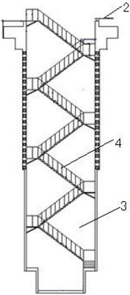
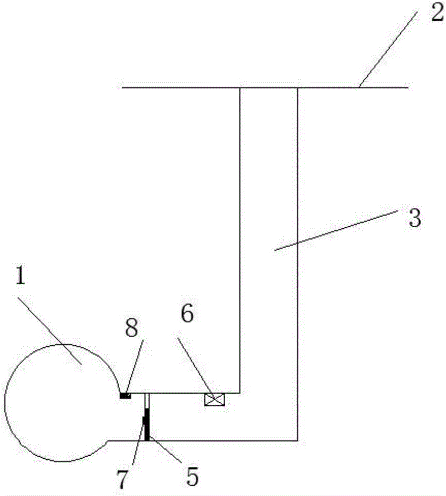
[0029] Shaft-type emergency exit structure system for intercity railway tunnels, consisting of a main tunnel 1 and a vertical shaft 3 connected to the tunnel main tunnel 1 at one end and set on the ground 2 at the other end. The height of the vertical shaft 3 does not exceed 30m, and the section is rectangular or circular;

[0030] Emergency communication 7 and video surveillance 8 are installed at the connection between the vertical shaft 3 and the main tunnel 1, and emergency lighting equipment is also installed in the vertical shaft 3, and the average horizontal illu...


PUM


Abstract

The invention provides a shaft type emergency exit structure system of an intercity railway tunnel. The shaft type emergency exit structure system comprises a vertical shaft arranged in the tunnel; the spacing between every two shafts arranged in the longitudinal direction of the tunnel does not exceed 5 km, the height of the shaft does not exceed 30 m, and the section of the shaft is rectangular or circular; various signs are arranged in the vertical shaft, including a staircase and a protective door; the minimum passage width of a stairway is not less than 0.8 m; a jet fan is mounted in the vertical shaft; the wind speed at the protective door is enabled not to be lower than 1.5 m / s. The shaft type emergency exit structure system provided by the invention is simple in structure, lower in requirements for an ground exit, small in section and short in length, does not occupy land resources and conforms to the relevant standards; the rectangular or circular section facilitates construction and meets the stairway arrangement requirements; the stairway width meets the requirements; meanwhile the protective door has the effect of resisting the train piston wind pressure; the jet fan can prevent smoke, and the timely startup of the fan in case of emergency can be ensured through three control modes; the system can ensure the evacuation safety, and the tunnel construction, operation and maintenance cost is reduced.

Description

technical field [0001] The invention belongs to the technical field of railway engineering construction, in particular to the technical field of railway tunnel safety engineering construction, and particularly relates to a design structure of a shaft-type emergency exit structure system of an intercity railway tunnel. Background technique [0002] With the rapid development of my country's railway construction, more and more extra-long railway tunnels with a length of more than 10km have appeared in recent years. Domestic scholars and design engineers have gradually realized the importance of railway tunnel disaster prevention, evacuation and rescue projects. Due to the constraints of the tunnel environment, construction auxiliary tunnels and other conditions, the emergency exits for evacuation generally adopt the structure of flat guides, horizontal holes, and inclined shafts, and vertical shafts are rarely used as emergency exits. Regarding the design method of shaft emerge...

Claims


Application Information

Patent Timeline
Patent Type & Authority Applications(China)
IPC IPC(8): E21D9/14E21F11/00E21F17/12E21F1/08
CPCE21D9/14E21F1/003E21F1/08E21F11/00E21F17/12
Inventor 王明年于丽代仲宇赵勇刘大刚田四明唐国荣
Owner SOUTHWEST JIAOTONG UNIV
Why Eureka
Try Eureka