Pipeline robot and application thereof

A pipeline robot and robot technology, applied in the field of robotics, can solve the problems of limited application occasions and inability of pipeline robots to generate sealing force, and achieve the effects of easy maintenance, good economic value and market benefits, and ingenious structural design

Active Publication Date: 2017-02-22
SHANDONG UNIV
View PDF6 Cites 7 Cited by
  • Summary
  • Abstract
  • Description
  • Claims
  • Application Information

AI Technical Summary

Problems solved by technology

However, the pipeline robot applied for in this patent cannot generate sealing force due to its structure, and cannot move in vertical pipelines, L-shaped pipelines, and T-shaped pipelines, so its application is limited

Method used


Image

  • Pipeline robot and application thereof
  • Pipeline robot and application thereof
  • Pipeline robot and application thereof

Examples


Embodiment 1

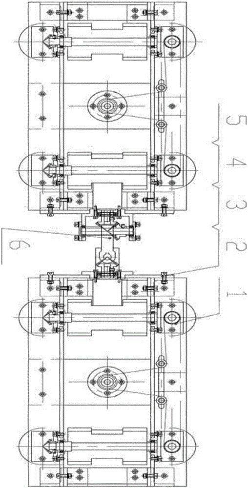
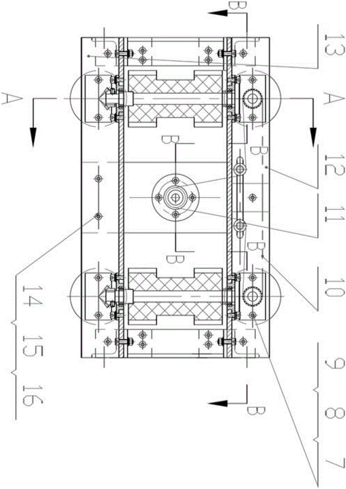
[0036] Such as Figure 1 to Figure 10 As shown, the present embodiment provides a pipe robot, which includes a robot unit, the robot unit includes a crawling mechanism 1 and a swing mechanism 6, and the swing mechanism 6 connects two crawling mechanisms 1 front and back;

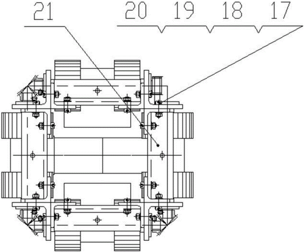
[0037] Among them, the crawling mechanism 1 includes a frame and a driving device. The frame is a rectangular parallelepiped frame structure consisting of a support frame and an angle steel frame. The angle steel frame is fixed and installed on the support frame by screws to form a rectangular parallelepiped structure. A12, three angle steel frames B13, and eight support frames 21 are composed of all angle steel frames A12, angle steel frames B13 and supports through hexagon socket head screws 17, flat washers 18, spring washers 19 and I-type hex nuts 20 The frame 21 is assembled into a cuboid structure. Two rotating shafts (eight rotating shafts in total, including six long shafts 24 and two short shafts 3...

Embodiment 2

[0047] A pipeline robot, the structure is as described in Embodiment 1, the difference is that: the belt drive train also includes a tensioning mechanism, the tensioning mechanism includes two tensioning shafts and two tensioning wheels, and the two tensioning shafts slide It is arranged on the frame, and the two tensioning wheels are respectively arranged at one end of the two tensioning shafts, and the synchronous belt bypasses the two tensioning wheels.

[0048] The tensioning mechanism 11 is mainly composed of a spacer 45, a tensioning shaft 46, and a deep groove ball bearing 47, and the position of the tensioning mechanism 11 on the angle steel frame A12 is adjusted through an I-type hex nut 42, a spring washer 43 and a flat washer 44. position, thereby adjusting the tension of the synchronous belt 10.

Embodiment 3

[0050] A working method of the pipeline robot as described in embodiment 2, comprising the following steps,

[0051] Place the pipeline robot in the pipeline to be operated, drive the motor 33 to run, and drive the rotating shaft (the long axis 24 and the short axis 31) to rotate through the belt transmission system. When the rotating shaft rotates, the driving wheel 30 advances in the pipeline;

[0052] When the pipeline robot needs to turn, the driving wheel 30 in contact with the pipeline is restrained by the inner wall of the pipeline, and the guiding driving wheel 30 turns and advances according to the bending direction of the pipeline; when turning, the robot swing mechanism 6 is not controlled by the swing motor 48 and can freely Swing, so as to avoid mutual restraint and influence between crawling mechanisms of the robot during the turning process;

[0053] When the pipeline robot needs to move in a vertical pipeline (such as an L-shaped or T-shaped pipeline), the two ...


PUM


Abstract

The invention relates to a pipeline robot and application thereof. The pipeline robot comprises one or more robot units which are sequentially connected, and each robot unit comprises two crawling mechanisms and a swing mechanism, wherein every two crawling mechanisms are connected to the front and the back of the corresponding swing mechanism; each crawling mechanism is mainly composed of a rack, a driving device, rotating shafts and driving wheels, wherein the driving device, the rotating shafts and the driving wheels are arranged on the rack; each swing mechanism is mainly composed of bevel gear systems which are meshed with each other and can achieve left-and-right swing and up-and-down swing. The pipeline robot is ingenious in structural design, simple and practical, operation of the crawling mechanisms can be driven through one driving motor, and meanwhile turning and obstacle crossing of the pipeline robot can be effectively achieved through the swing mechanisms; compared with an existing pipeline robot on the market, the pipeline robot is low in cost, stable and reliable to operate and convenient to maintain, operation work in multiple complicated occasions such as vertical pipelines, L-shaped pipelines and T-shaped pipelines can be achieved, and good economic value and market benefit are achieved.

Description

technical field [0001] The invention relates to a pipeline robot and its application, in particular to a wheeled pipeline robot, which belongs to the technical field of robots. Background technique [0002] Pipes are widely used in machinery, chemical industry, energy, nuclear power and other industrial fields, and are one of the important transportation tools. Industrial transportation pipelines are generally in a harsh environment for a long time, which is prone to damage such as blockage, rupture, deformation, etc., seriously affecting normal production and operation and even causing safety accidents. In order to ensure the normal operation of transportation pipelines, pipelines can be used Robots regularly inspect and maintain pipelines. However, there are foreign objects such as oil and mud in most of the pipelines, and the pipeline structure is complex, such as T-shaped, L-shaped, U-shaped and other complex structures, which require high motion performance for pipelin...

Claims


Application Information

Patent Timeline
Patent Type & Authority Applications(China)
IPC IPC(8): F16L55/28F16L101/30F16L101/10
CPCF16L55/28F16L2101/10F16L2101/30
Inventor 周军韩猛桑迪赵峰翟科栋
Owner SHANDONG UNIV
Why Eureka
Try Eureka