
Direction-of-arrival (DOA) angle estimation method based on dual-layer nested array

A direction-of-arrival and double-layer nesting technology, which is applied in the field of signal processing, can solve the problems that the maximum utilization rate of array elements cannot be achieved without reasonable setting of array element positions, waste of reconnaissance and positioning resources, target reconnaissance, and inability to estimate enough signals, etc. , to avoid target reconnaissance errors, improve array utilization, and improve the effect of low signal-to-noise ratio

Active Publication Date: 2017-02-22
XIDIAN UNIV
View PDF2 Cites 16 Cited by
  • Summary
  • Abstract
  • Description
  • Claims
  • Application Information

AI Technical Summary

Problems solved by technology

However, this method is equivalent to using a uniform array to expand the nested array, and the position of the array element is not set properly so that the array element cannot reach the maximum utilization rate.
In practical applications, if a certain number of array elements are given, but these array elements cannot be reasonably used to obtain enough virtual array elements, enough signals cannot be estimated, resulting in waste of reconnaissance and positioning resources and errors in angle estimation. target detection error

Method used


Image

  • Direction-of-arrival (DOA) angle estimation method based on dual-layer nested array
  • Direction-of-arrival (DOA) angle estimation method based on dual-layer nested array
  • Direction-of-arrival (DOA) angle estimation method based on dual-layer nested array

Examples


Embodiment Construction

[0033] The technical solutions and effects of the present invention will be further described in detail below with reference to the accompanying drawings.

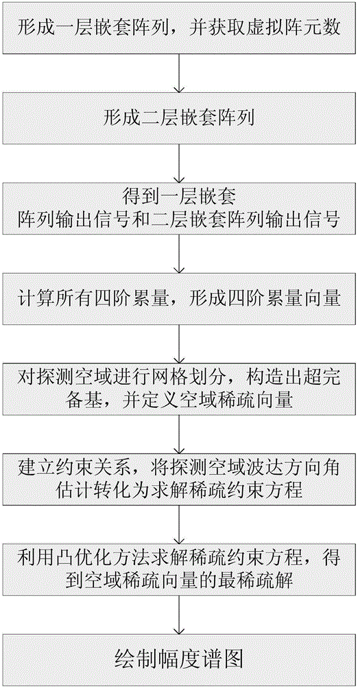
[0034] attached figure 1 , the concrete steps of the present invention are as follows:

[0035] Step 1: Use the antenna receiver to form the first layer of nested arrays, and obtain the number of virtual array elements.

[0036] (1a) Define each antenna receiver as an array element, use M antenna receivers to form a first uniform linear array a, and its array element spacing is d; use N antenna receivers to form a second uniform linear array b, its The array element spacing is (M+1)d; define the first array element of the first uniform linear array a as the initial array element, where, M≥1, N≥1, 0<d≤λ / 2, λ is the wavelength of the narrowband signal incident on the nested array;

[0037] (1b) Combining the first uniform linear array a and the second uniform linear array b into the first layer of nested arrays:

[0038]...


PUM


Abstract

The invention discloses a direction-of-arrival (DOA) angle estimation method based on a dual-layer nested array and mainly aims at solving the problems of heavy computation, low quantity of identified information sources and great estimation error in the prior art. The DOA angle estimation method comprises the following implementation steps: firstly, respectively constructing a first-layer nested array and a second-layer nested array; secondly, acquiring an output signal of the first-layer nested array and an output signal of the second-layer nested array; thirdly, calculating all fourth-order cumulants according to the output signal of the first-layer nested array and the output signal of the second-layer nested array to form a fourth-order cumulant vector; fourthly, constructing an over-complete base according to the fourth-order cumulant vector, and defining an airspace sparse vector; fifthly, converting detection of an airspace DOA angle estimation into solving of a sparse constraint equation; sixthly, obtaining a most sparse solution of the airspace sparse vector by using a convex optimization method; seventhly, drawing an amplitude spectrum according to the most sparse solution to obtain the DOA angle. According to the DOA angle estimation method disclosed by the invention, the quantity of information sources which can be identified is greatly increased under the condition of limited array element quantity; the DOA angle estimation method can be used for target reconnaissance and passive location.

Description

technical field [0001] The invention belongs to the technical field of signal processing, in particular to a method for estimating the direction of arrival angle of array signals of electromagnetic signals, which can be used for reconnaissance and passive positioning of moving targets of aircraft and ships. Background technique [0002] Signal DOA estimation is an important branch in the field of array signal processing. It refers to the use of antenna arrays to inductively receive spatial acoustic signals and electromagnetic signals, and then use modern signal processing methods to quickly and accurately estimate the direction of the signal source. , has important application value in radar, sonar, wireless communication and other fields. With the continuous advancement of science and technology, there are higher and higher requirements for the degree of freedom that the array can achieve when estimating the signal direction of arrival. [0003] In the research on this pro...

Claims


Application Information

Patent Timeline
IPC IPC(8): G01S3/46G06F17/16
CPCG01S3/46G06F17/16
Inventor 蔡晶晶宗汝王振华李鹏赵晗希
Owner XIDIAN UNIV
Learn More