Image forming device and sheet conveying device
A sheet and image technology, applied in the field of image forming devices, can solve the problems of increasing the interval between sheets and reducing productivity, and achieve the effect of precise sheet interval
- Summary
- Abstract
- Description
- Claims
- Application Information
AI Technical Summary
Problems solved by technology
Method used
Image
Examples
Embodiment 1
[0021] image forming device
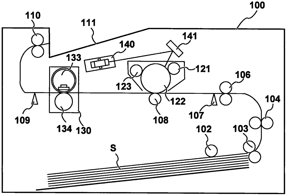
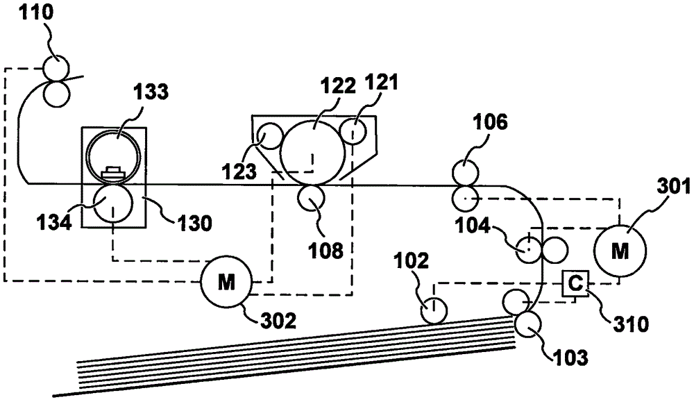
[0022] figure 1 is a schematic cross-sectional view of the image forming apparatus 100 . Although the image forming apparatus 100 according to the present embodiment is a printer employing an electrophotographic method, an image forming apparatus applicable to the present invention may employ other image forming methods such as an inkjet method or a thermal transfer method. The photosensitive drum 122 serves as a photosensitive element and an image carrier, and rotates in a clockwise direction at a predetermined peripheral speed (process speed) vps. The charging roller 123 uniformly charges the surface of the photosensitive drum 122 . The optical scanning device 140 outputs light beams according to image signals. The light beam is reflected by the mirror 141, irradiates the surface of the photosensitive drum 122, and forms an electrostatic latent image. The developing roller 121 develops the electrostatic latent image by adhering toner thereto...
Embodiment 2
[0068] In Embodiment 1, the method for determining the reduction amount Q is selected by using the difference Δ between the sheet length measurement result Lmsr of the previous sheet and the nominal value specified by the operator. Embodiment 1 is based on the premise that the operator designates the correction size of the sheet S. Therefore, if the operator designates an incorrect size, the reduction amount Q cannot be correctly determined. In view of the above problems, Embodiment 2 describes an example in which the reduction amount is determined according to the range of the measurement error measured in advance. Note that the description of the matters common to Embodiment 2 and Embodiment 1 is omitted.
[0069] refer to Figure 4A to Figure 4F As mentioned above, the gyro sensor 107 has a marker 402, an optical chopper 401, a spring 407, and the like. Therefore, the following factors may cause sheet spacing measurement errors:
[0070] - Tolerances for the shape of th...
Embodiment 3
[0083] In Embodiments 1 and 2, the sheet sensor 400 having the optical chopper 401 and the marker 402 is described as the gyro sensor 107 . However, other types of sheet sensors may be employed with the present invention. In Embodiment 3, a rotating sheet sensor is described. Note that descriptions of matters common to Embodiment 3 and Embodiments 1 and 2 are omitted.
[0084] Figure 8A to Figure 8F is a diagram illustrating the configuration and operation of the rotating sheet sensor 400'. The sheet sensor 400" has: a shaft 904 serving as a center of rotation; a mark 902 for detecting a sheet S; a light chopper mark 903; and a light chopper 901. The mark 902 and the mark 903 are fixed to the shaft 904, Assume that the sheet S is conveyed from right to left along the conveyance guide 404 .
[0085] Figure 8A The sheet sensor 400' in a state where the sheet S is not fed is shown. exist Figure 8A , the marker 902 is at its original position. In a state where the sheet...
PUM
 Abstract
Description
Claims
Application Information
 - R&D
- Intellectual Property
- Life Sciences
- Materials
- Tech Scout
- Unparalleled Data Quality
- Higher Quality Content
- 60% Fewer Hallucinations
Browse by: Latest US Patents, China's latest patents, Technical Efficacy Thesaurus, Application Domain, Technology Topic, Popular Technical Reports.
© 2025 PatSnap. All rights reserved.Legal|Privacy policy|Modern Slavery Act Transparency Statement|Sitemap|About US| Contact US: help@patsnap.com


