A simply supported beam vibration experiment demonstration instrument

A technology of simply supported beams and demonstrators, applied in instruments, educational appliances, teaching models, etc., can solve the problems of high speed, lack of intuition, small amplitude, etc., and achieve the effect of deepening understanding

Inactive Publication Date: 2018-04-06
厉子宁
View PDF4 Cites 2 Cited by
  • Summary
  • Abstract
  • Description
  • Claims
  • Application Information

AI Technical Summary

Problems solved by technology

[0005] Since the amplitude of each point is small and the speed is fast during the vibration process of the simply supported beam, it is difficult to observe the mode shapes of each order intuitively.
In the existing experiments, the displacement of each point is often recorded by the strain sensor, and the recorded data is drawn on the coordinates as a graph corresponding to the main vibration mode, so as to facilitate observation. However, this observation method lacks intuition due to the intermediate processing of the data.

Method used


Image

  • A simply supported beam vibration experiment demonstration instrument
  • A simply supported beam vibration experiment demonstration instrument
  • A simply supported beam vibration experiment demonstration instrument

Examples


Embodiment 1

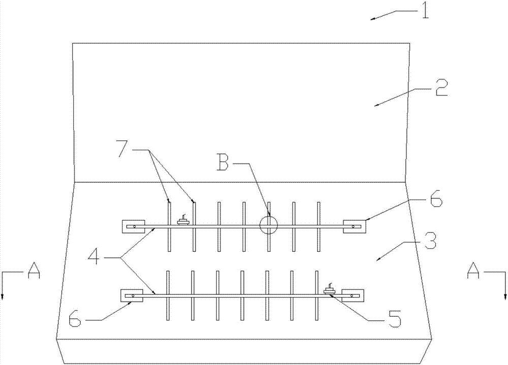
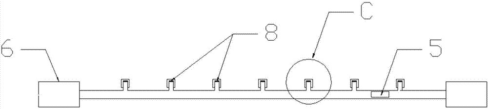
[0035] Provided in the present invention is a simply supported beam vibration experiment demonstrator, comprising a test box 1, a test box cover 2, a beam body 4 arranged in the test box 1, two ends of the beam body 4 are simply supported by supports 6, and the beam The side of the body 4 is provided with the bottom plate 3 of the experimental box, and the upper surface of the beam body 4 is provided with a vibrator 5 body, which provides vibration excitation force to the beam body 4 through its own vibration, and the beam body 4 is under the action of the excitation force. , vibrate up and down in the plane where the bottom plate 3 of the test box is located.

[0036] A plurality of protruding teeth 8 are arranged on the side of the beam body 4, and a plurality of displacement display grooves 7 are fixed on the bottom plate 3 of the experiment box. The position of the display groove 7 corresponds to the position of the convex teeth 8 of the beam body 4, and the convex teeth 8...

Embodiment 2

[0045]Provided in the present invention is a simply supported beam vibration experiment demonstrator, comprising an experiment box 1, a beam body 4 arranged in the experiment box 1, two ends of the beam body 4 are simply supported by supports 6, and the beam body 4 side is provided with an experiment The bottom plate 3 of the box 1 and the upper surface of the beam body 4 are provided with a vibrator 5 body, which provides a vibration excitation force to the beam body 4 through its own vibration, and the beam body 4 is under the action of the excitation force. The bottom plate 3 vibrates up and down in the plane.

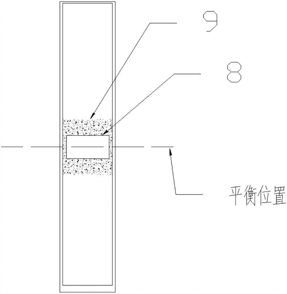
[0046] A plurality of convex teeth 8 are arranged on the side of the beam body 4, and a plurality of displacement display grooves 7 are fixed above the bottom plate 3 of the experiment box 1. The display groove is a rectangular groove body arranged in the quilt plate, and iron sand powder 9 is arranged in the groove body, and the displacement display The position of...


PUM


Abstract

The invention aims to provide a demonstrating instrument for a simply supported beam vibration experiment. In a physics teaching process, vibration of an infinite-degree-of-freedom object is usually demonstrated through vibrations of simply supported beams or cantilever beams. The simply supported beams in the demonstrating instrument vibrate under vibration excitations of vibration exciters, when the vibration excitation frequency equals to an inherent frequency of a specific phase, the beams resonate, and the vibrating form is approximate to a corresponding principal vibration mode. When the vibration excitation frequency of the vibration exciters is increased slowly, variation of the beams from a first-phase principal vibration mode to a second-phase and a third-phase principal vibration mode can be shown. The demonstrating instrument for the simply supported beam vibration experiment has the advantages that by amplifying displacement and vibration of the simply supported beams by directly demonstrating the principal vibration modes in various phases of the simply supported beams, experimental explanation in modeled teaching for the infinite-degree-of-freedom object vibration is facilitated, and by comparing and observing the multi-phase vibration modes, understanding to modal superposition on vibration is enhanced.

Description

technical field [0001] The invention belongs to the field of physics teaching appliances, in particular to a simply supported beam vibration experiment demonstration, belonging to teaching experiment appliances. Background technique [0002] In the process of physics teaching, the model of a spring oscillator is generally used to demonstrate the vibration of a single-degree-of-freedom object. For the vibration of an object with infinite degrees of freedom, it is generally demonstrated by a simply supported beam or a cantilever beam. [0003] During the vibration process of an object with infinite degrees of freedom, its natural frequency and main vibration mode are two important parameters to describe the vibration, which are only related to the nature of the structure itself and reflect the inherent properties of the structure. The so-called main vibration shape is the vibration displacement ratio of each point on the vibrating body at the same time, and its main vibration...

Claims


Application Information

Patent Timeline
Patent Type & Authority Patents(China)
IPC IPC(8): G09B23/10
CPCG09B23/10
Inventor 厉子宁
Owner 厉子宁
Why Eureka
Try Eureka