
a magnetic element

A technology of magnetic components and magnetic cores, applied in electrical components, parts of transformers/inductors, circuits, etc., can solve problems affecting performance and life, magnetic components without heat dissipation structures, secondary copper sheet windings and primary windings The relative position cannot be accurately positioned, etc., to achieve the effect of enhancing heat dissipation and flow, and realizing modular expansion

Active Publication Date: 2019-01-15
SHENZHEN VMAX NEW ENERGY CO LTD
View PDF12 Cites 1 Cited by
  • Summary
  • Abstract
  • Description
  • Claims
  • Application Information

AI Technical Summary

Problems solved by technology

[0004] 1. The primary winding needs to be wound manually. When the number of turns is large, the consistency of the winding size cannot be guaranteed;
[0005] 2. The relative position of the secondary copper sheet winding and the primary winding cannot be accurately positioned, especially after multiple primary and secondary windings are sandwiched, batch consistency is difficult to guarantee;
[0006] 3. There is no effective heat dissipation structure on the magnetic element, and the heat cannot be dissipated quickly when the magnetic element is in use, which affects the performance and life of the magnetic element

Method used


Image

  • a magnetic element
  • a magnetic element
  • a magnetic element

Examples


Embodiment Construction

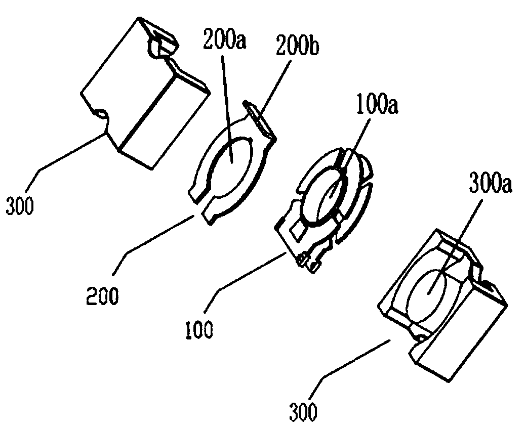
[0030] Such as figure 2 , 6 As shown in , 9 , the magnetic element proposed by the present invention includes: a winding bobbin 100 , a magnetic core group and a conductive winding 200 .

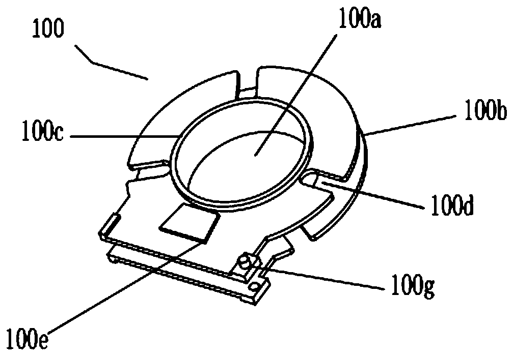
[0031] The main body of the bobbin 100 is a flat disc, and the center of the disc is provided with an installation channel 100a that runs through both ends of the disc. The side of the bobbin 100 is recessed inward to form a wire groove 100b, and the wire groove 100b surrounds the installation channel 100a. The setting of the outer ring and the wire groove 100b can realize the automatic winding process. The magnetic core group is composed of two butted magnetic cores 300 on the left and right, and at least one of the magnetic cores 300 is provided with a mounting post 300a that can be inserted into the mounting channel 100a. In actual application, the two magnetic cores 300 in the magnetic core group can be symmetrically arranged left and right, and the two magnetic cores 300 are provided...


PUM


Abstract

The invention discloses a magnetic element. The magnetic element comprises a winding skeleton, a magnetic core group and a conducting winding, wherein a mounting channel passing through two ends of the winding skeleton is arranged at the center of the winding skeleton, the side face of the winding skeleton is depressed inwards to form a wire slot encircling the outer ring of the mounting channel, and locating rings protruding outwards are arranged at the centers of two end faces of the winding skeleton respectively; the magnetic core group is composed of two magnetic cores sleeved at two ends of the winding skeleton; the conducting winding is arranged on at least one end face of the winding skeleton, locating holes capable of being sleeved on the locating rings are formed in the conducting winding, a bending part is further arranged on one side edge of the conducting winding, and the bending part stretches out of the magnetic core group. The magnetic element is provided with an effective heat dissipation structure, and a primary winding and a secondary winding can be accurately positioned, so that the magnetic element is convenient for volume automatic production.

Description

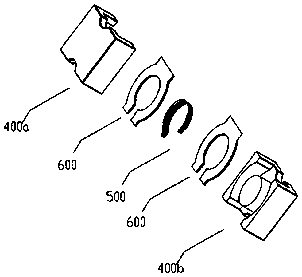
technical field [0001] The invention relates to the technical field of magnetic components, in particular to a magnetic component with a cooling and positioning structure. Background technique [0002] The current design of magnetic components of switching power supplies, such as transformers, etc., in order to reduce the size of the device, often use figure 1 In the shown structure, a transformer is formed by combining the primary winding 500 and the secondary copper winding 600, and then cooperating with the magnetic cores 400a and 400b. The primary side of the transformer is usually high-voltage and low-current, which requires more winding turns. The secondary side of the transformer is low-voltage and high-current, which requires fewer winding turns. Copper sheet windings are generally used. [0003] This scheme has the following disadvantages: [0004] 1. The primary winding needs to be wound manually. When the number of turns is large, the consistency of the winding ...

Claims


Application Information

Patent Timeline
Patent Type & Authority Patents(China)
IPC IPC(8): H01F27/28H01F27/30H01F27/08
CPCH01F27/2847H01F27/2876H01F27/306
Inventor 刘钧徐鹏华
Owner SHENZHEN VMAX NEW ENERGY CO LTD
Learn More