
A Modular Local Resonance Type Phononic Crystal Vibration Isolation Pad

A technology of local resonance and phononic crystals, which is applied in the direction of shock absorbers, springs/shock absorbers, shock absorbers, etc., can solve the problems of small period number of periodic materials, limited working space, and insignificant vibration isolation effect, etc. Achieve outstanding vibration isolation effect, wide application range, and realize the effect of modular expansion

Inactive Publication Date: 2016-05-18
HARBIN INST OF TECH
View PDF4 Cites 0 Cited by
  • Summary
  • Abstract
  • Description
  • Claims
  • Application Information

AI Technical Summary

Problems solved by technology

[0006] The present invention aims to solve the problems that the period number of the periodic material of the current phononic crystal vibration isolator is small, the vibration isolation effect is not obvious, and the working space is limited, and further provides a modular local resonance type phononic crystal vibration isolation pad

Method used


Image

  • A Modular Local Resonance Type Phononic Crystal Vibration Isolation Pad
  • A Modular Local Resonance Type Phononic Crystal Vibration Isolation Pad
  • A Modular Local Resonance Type Phononic Crystal Vibration Isolation Pad

Examples


specific Embodiment approach 1

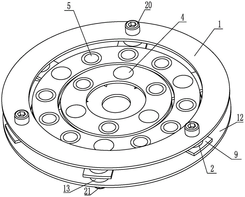
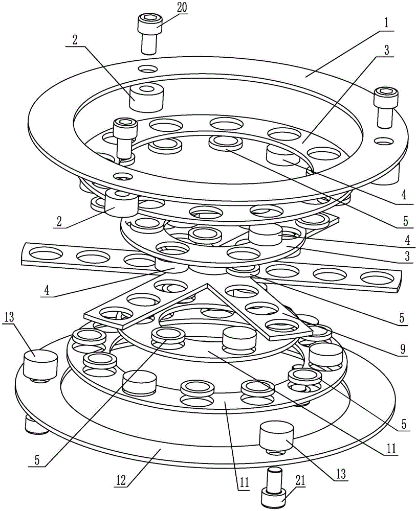
[0015] Specific implementation mode one: combine Figure 1-Figure 3 Explain that a modular local resonance type phononic crystal vibration isolation pad in this embodiment includes a vibration input support 1, a main body support frame 9, a vibration output support 12, a plurality of vibration input support connecting columns 2, multiple A vibration output support connects the cylinder 13 and the N-level local resonance type phononic crystal component, wherein N is a positive integer, and N≥2;

[0016] The vibration input support 1 is located above the vibration output support 12, between the vibration input support 1 and the vibration output support 12, N-level local resonance type phononic crystal components are arranged sequentially from outside to inside, and the N-level local resonance The type phononic crystal components are arranged between the N-1 level local resonance type phononic crystal components;

[0017] Each level of local resonance type phononic crystal assem...

specific Embodiment approach 2

[0022] Specific implementation mode two: combination figure 1 and figure 2 Explain that the vibration input support 1 and the vibration output support 12 of this embodiment are both circular structures, and the vibration isolation upper support 3 and the vibration isolation lower support 11 in each level of local resonance type phononic crystal assembly are both It is a circular structure. Such an arrangement has a simple structure and a reasonable design, which is beneficial to the optimal layout of the multi-level local resonance type phononic crystal. Others are the same as in the first embodiment.

specific Embodiment approach 3

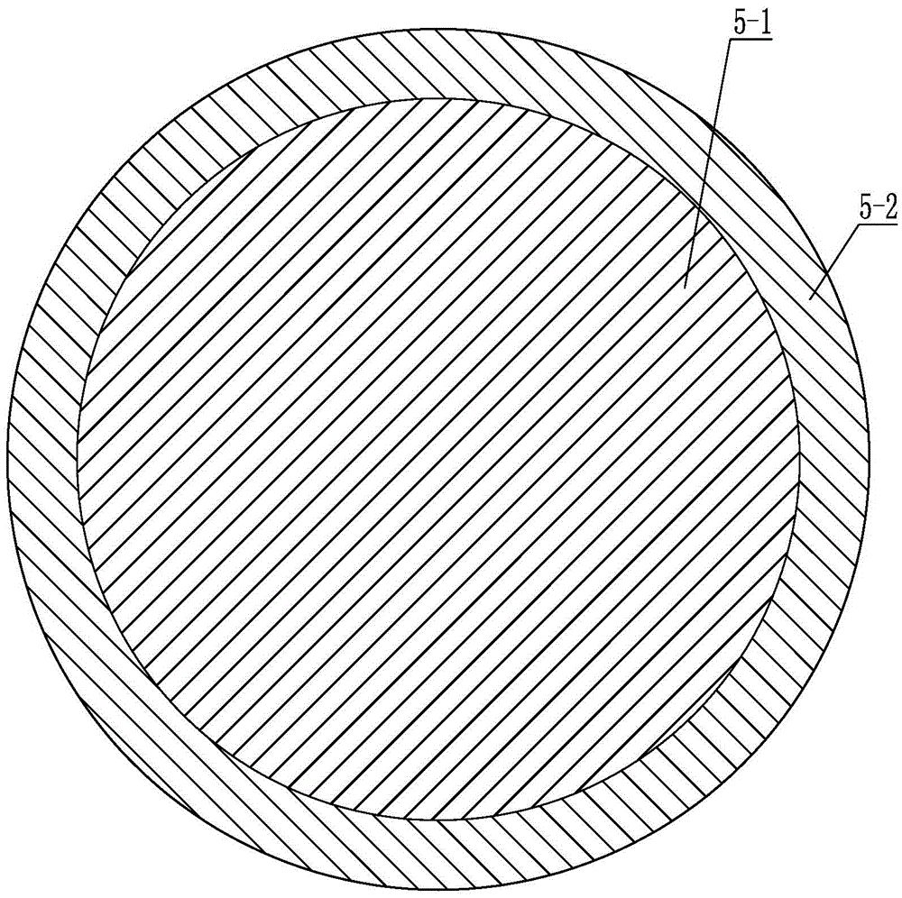
[0023] Specific implementation mode three: combination figure 2 and image 3 Note that the vibration-isolation upper support 3 and the vibration-isolation lower support 11 of each level of local resonance type phononic crystal components in this embodiment are respectively processed with the number of local resonance type phononic crystal local oscillators 5 arranged respectively. A plurality of first circular through holes are consistent, and the local resonance type phononic crystal local oscillator 5 is glued in the first circular through holes. With such setting, the connection is reliable and the structure is stable and reasonable. Others are the same as in the first or second embodiment.


PUM


Abstract

The invention relates to vibration isolation pads in the field of vibration isolation and noise reduction, in particular to a modular local resonance type photonic crystal vibration isolation pad which aims to solve the problems that cycle materials of an existing photonic crystal vibration isolator are small in cycle number, unobvious in vibration isolation effect, and the work space is restricted. The modular local resonance type photonic crystal vibration isolation pad comprises a vibration input support, a main body support framework, a vibration output support, a plurality of vibration input support connection column bodies, a plurality of vibration output support connection column bodies and N levels of local resonance type photonic crystal assembles. The vibration input support is located above the vibration output support, each level of the local resonance type photonic crystal assembly comprises an upper vibration isolation support, a lower vibration isolation support, a plurality of vibration isolation connection column bodies and a plurality of local resonance type photonic crystal local oscillators. The vibration input support connection column bodies and the vibration output support connection column bodies are connected with the main body support framework respectively. The modular local resonance type photonic crystal vibration isolation pad is used for vibration isolation.

Description

technical field [0001] The invention relates to a vibration isolation pad in the field of vibration isolation and noise reduction. Background technique [0002] There are various vibration problems in the machinery industry and other industrial sectors, many of which are harmful vibrations. Excessive vibration and noise caused by vibration will pollute the environment and damage people's health. [0003] Vibration isolation (referred to as vibration isolation) is the most widely used vibration reduction technology in vibration control. The so-called vibration isolation refers to taking certain measures between the vibration source and the system, and installing appropriate vibration isolation equipment to isolate the direct transmission of vibration. The essence is to add a subsystem (vibration isolator) between the vibration source and the system. From an energy point of view, vibration isolation is to change the energy spectrum structure of the vibration source exciting t...

Claims


Application Information

Patent Timeline
Patent Type & Authority Patents(China)
IPC IPC(8): F16F7/00
Inventor 郭宏伟赵浩江邓宗全刘荣强史创
Owner HARBIN INST OF TECH
Learn More