Rotation angle detecting sensor

a detection sensor and rotation angle technology, applied in the direction of measuring devices, instruments, using electrical means, etc., can solve the problems of dense connection between adjacent coils, and achieve the effects of reducing interaction and increasing distance between two adjacent inductance elements

Inactive Publication Date: 2010-12-09
SUMIDA CORP
View PDF8 Cites 15 Cited by
  • Summary
  • Abstract
  • Description
  • Claims
  • Application Information

AI Technical Summary

Benefits of technology

[0015]Further, in the rotation angle detecting sensor according to the present invention, the plurality of inductance elements have a phase difference of 90 degrees therebetween, and the two adjacent inductance elements are disposed apart from each other by a space of at least half a phase of the encoder structure. With such a configuration, the distance between two adjacent inductance elements can be increased compared with a configuration in which the inductance elements are collectively disposed in one phase of the encoder structure with a space of ¼ of a phase.
[0016]According to the present invention, since the distance between two adjacent inductance elements can be increased,

Problems solved by technology

Thus, when trying to reduce the diameter of the sensor or to increase the cycle numb

Method used


Image

  • Rotation angle detecting sensor
  • Rotation angle detecting sensor
  • Rotation angle detecting sensor

Examples


Embodiment Construction

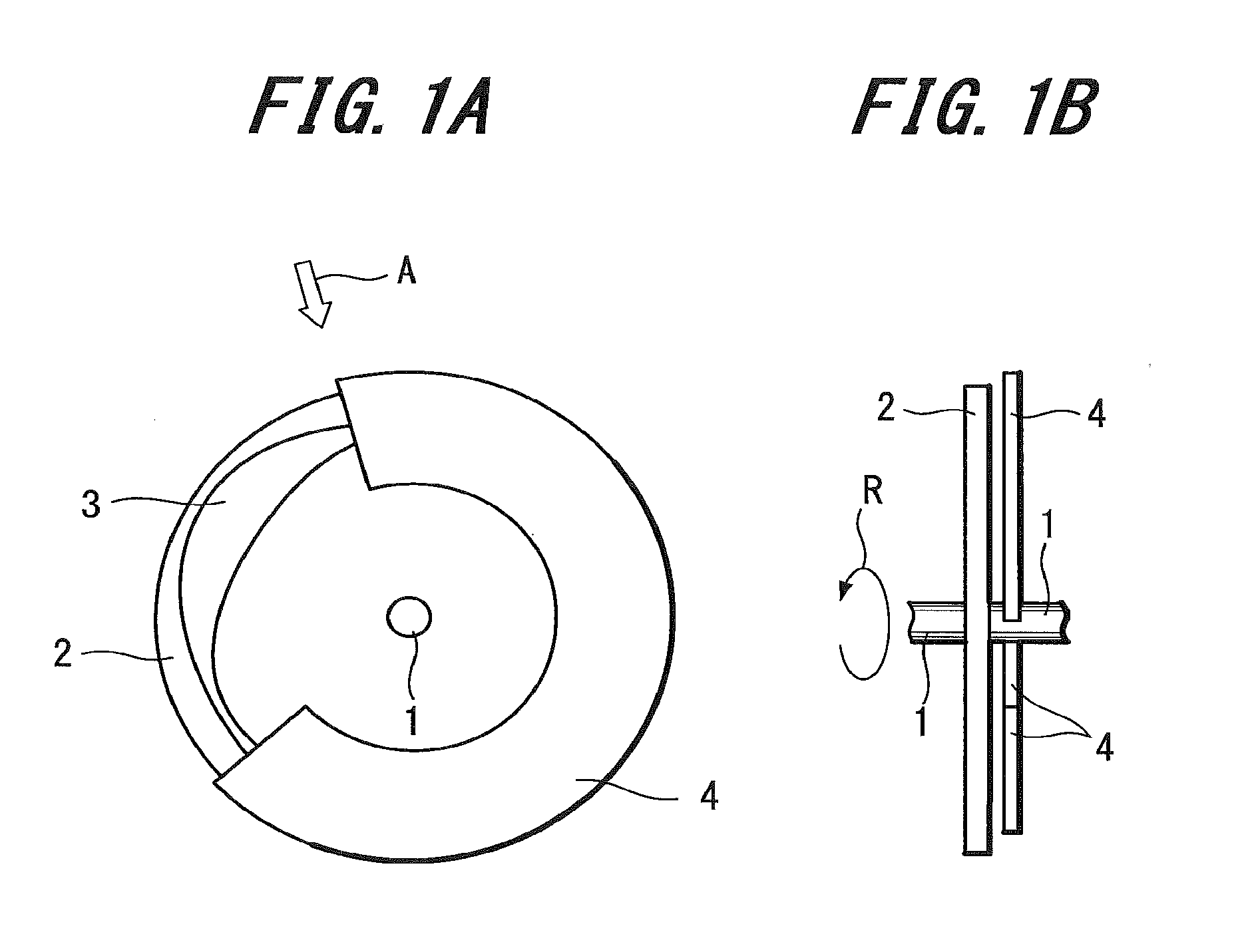
[0038]FIGS. 1A and 1B are views schematically showing the configuration of a rotation angle detecting sensor according to an embodiment of the present invention. FIG. 1A is a plan view, and FIG. 1B is a side view seen from the direction indicated by arrow A of FIG. 1A.

[0039]As shown in FIGS. 1A and 1B, a circular plate-like rotor 2 is attached to a bar-like rotating shaft 1.

[0040]The rotor 2 rotates around the rotating shaft 1 as shown by arrow R of FIG. 1B.

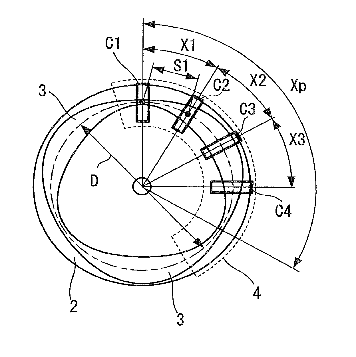
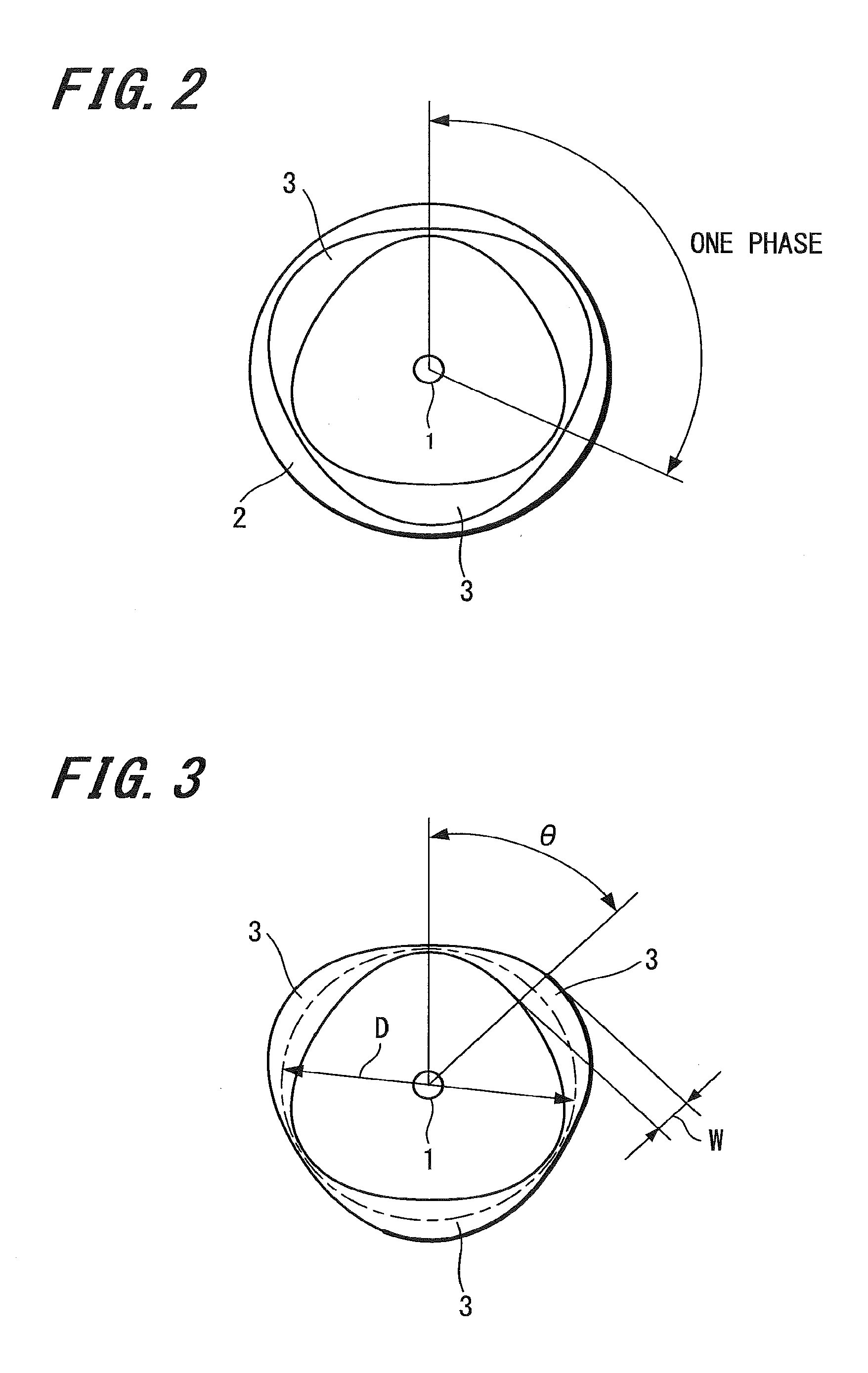
[0041]Further, an encoder structure 3 configured by a conductor pattern is formed on a surface of the rotor 2.

[0042]Further, a sensor body 4 of the rotation angle detecting sensor is provided opposing the surface of the rotor 2 on which the encoder structure 3 is formed.

[0043]The sensor body 4 is a C-shaped member extending along a circular arc with the rotating shaft 1 as the center. Further, the sensor body 4 is fixed by a member not shown in the drawing, and the encoder structure 3 of the rotor 2 is configured so that the posi...


PUM


Abstract

The present invention is made to provide a rotation angle detecting sensor capable of being miniaturized.
The rotation angle detecting sensor includes a rotating body; an encoder structure 3 having n (n represents a positive integer) cycles of phases each ranging from phase 0° to phase 360°, each phase being formed by periodically changing the width of the conductor pattern; and a sensor body having a plurality of inductance elements C1, C2, C3, C4 and disposed opposing the encoder structure 3 with a space. The cycle number n of the phase of the encoder structure 3 is a positive integer equal to or greater than three, the plurality of inductance elements C1, C2, C3, C4 have a phase difference of 90 degrees therebetween, and the two adjacent inductance elements are disposed apart from each other by a space of at least half a phase of the encoder structure 3.

Description

TECHNICAL FIELD[0001]The present invention relates to a rotation angle detecting sensor for detecting the position of a rotating body such as a rotor of a motor.BACKGROUND ART[0002]In a brushless DC motor, rectification control is performed by switching the direction of a current flowing in a stator. In order to perform such a rectification control, it is necessary to obtain angle information of the rotor, and therefore an angle sensor for detecting the angle of the rotor is provided (see, for example, Patent Document 1).[0003]The angle sensor is generally based on a method for detecting the magnetic field of a permanent magnet of the rotor.[0004]In contrast, in the case where finer control is necessary, a rotation angle detecting sensor based on eddy current loss principle, as disclosed in Patent Document 1, is used.[0005][Patent Document 1] German Utility Model 20 2006 008 962 U1DISCLOSURE OF THE INVENTION[0006]In the art disclosed in Patent Document 1, an encoder structure config...

Claims


Application Information

Patent Timeline
IPC IPC(8): G01B7/30
CPCG01D1/00G01D5/2013G01D21/00G01D15/00G01D5/202G01D2205/77G01B7/30
Inventor YAMAGATA, TETSUONAGASAWA, HIROAKI
Owner SUMIDA CORP
Why Eureka
Try Eureka